Software for Windows
Science with your Sound Card!


Features:
Oscilloscope
Spectrum Analyzer
8-Channel
Signal Generator
(Absolutely FREE!)
Spectrogram
Pitch Tracker
Pitch-to-MIDI
DaqMusiq Generator
(Free Music... Forever!)
Engine Simulator
LCR Meter
Remote Operation
DC Measurements
True RMS Voltmeter
Sound Level Meter
Frequency Counter
Period
Event
Spectral Event
Temperature
Pressure
MHz Frequencies
Data Logger
Waveform Averager
Histogram
Post-Stimulus Time
Histogram (PSTH)
THD Meter
IMD Meter
Precision Phase Meter
Pulse Meter
Macro System
Multi-Trace Arrays
Trigger Controls
Auto-Calibration
Spectral Peak Track
Spectrum Limit Testing
Direct-to-Disk Recording
Accessibility
Data Logger
Waveform Averager
Histogram
Post-Stimulus Time
Histogram (PSTH)
THD Meter
IMD Meter
Precision Phase Meter
Pulse Meter
Macro System
Multi-Trace Arrays
Trigger Controls
Auto-Calibration
Spectral Peak Track
Spectrum Limit Testing
Direct-to-Disk Recording
Accessibility
Applications:
Frequency response
Distortion measurement
Speech and music
Microphone calibration
Loudspeaker test
Auditory phenomena
Musical instrument tuning
Animal sound
Evoked potentials
Rotating machinery
Automotive
Product test
Contact us about
your application!
Making Waves via Sine Wave Synthesis
Any waveform can be synthesized from pure sinusoids. You can use the Daqarta Generator to demonstrate the basics of this by generating the fundamental and first few harmonics of square, ramp, or triangle waves.
Although only 4 sines are used in these examples, note that you can use up to 8 via the Multi-Channel Output Controls, even if you only have a 2-channel sound card. Also note that the Sine Series section of the Arb_From_Equation macro mini-app shows how to create each of these series with an arbitrary number of sines, all embodied in a single Arb waveform.
The Fourier series for a square wave consists of the fundamental plus all odd harmonics, such that the amplitude of the Nth harmonic is 1/N of the fundamental amplitude. For a fundamental of frequency F and amplitude A, the series would be:
    Freq    Amplitude
    F       A
    3*F     A/3
    5*F     A/5
    7*F     A/7
    ...
    N*F     A/N     (odd N only)
Toggle the Left output on and the Right off. Set the Left Stream 0 component to be the fundamental frequency... we'll use 100 Hz in this example:
Stream On
Wave = Sine
Tone Freq = 100
Modulators all off
Level = 100.00%
DC Offset = 0
Now set Stream 1 to be the 3rd harmonic, with Tone Freq = 300 and Level = 33.33%, which is 1/3 of the fundamental. Stream 2 will be the 5th harmonic with a Level of 20% and Stream 3 the 7th at 14.29%.
(Alternatively, you can load the SineSqr.GEN setup that is included with Daqarta, which already has everything set.)
As you add each harmonic, you will see the initial sine wave get steeper sides, and the ripples at the peaks get smaller, approaching a square wave:
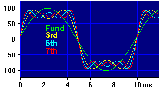
Notice how each higher harmonic acts to reduce the ripples by providing a complementary wave that fills in dips and rounds off peaks. Although a perfect square wave requires an infinite number of harmonics, it should be clear that if you extended this process you could approximate one to any desired degree of precision.
Notice also that the addition of odd harmonics reduces the peak of the fundamental. This leads to the surprising result that a perfect square wave has a fundamental that is 1.27 times the peak amplitude of the square wave itself (+2.07 dB).
You can also see the beginnings of Gibbs phenomenon, the "bat ears" and ripples that appear on the corners of the (eventual) square wave. As you add more odd harmonics to get a better square wave, these ears become sharper (narrower and hence less noticeable compared to the broader flat portion). But, curiously, the peaks never go below about 9% overshoot with any finite number of harmonics.
You may wish to experiment with other wave shapes, like ramps or triangles. A ramp is made just like the square wave, only using all integer harmonics, not just the odd ones. So the 2nd harmonic is 1/2 the fundamental, the 3rd is 1/3, and the 4th is 1/4. Set the fundamental level to 50% instead of 100% and scale the other components proportionally, since otherwise the waveform would have peaks exceeding 100%.
This will be a "descending" ramp, with the steep side on the left. An identical ramp shifted 90 degrees relative to this can be made by setting the phase of the odd components to 180 degrees. If you want to see both ramps at the same time for comparison, you can build the other one on the Right output.
To reverse the ramp to an "ascending" version, you can set all the phases to 180 degrees. A shifted ascending ramp results if the odd components are set to 0 degrees and the evens are at 180.
A triangle is made with only odd harmonics, but instead of falling off proportional to the reciprocal of frequency like the square wave, they fall off with the square of the reciprocal. In addition, the phase changes between 0 and 180 degrees with each harmonic used. Again, you will need to start at a reduced level to avoid going over 100%. Try this:
Stream   Freq   Phase    Level
    0     100      0     50.00
    1     300    180      5.56    (50 / 3^2)
    2     500      0      2.00    (50 / 5^2)
    3     700    180      1.02    (50 / 7^2)
See also Sine Wave Basics, Sine Wave Phase, Magnitude via Vector Sum
- Back to Magnitude via Vector Sum
- Ahead to Sound Card Performance Tests
- Daqarta Help Contents
- Daqarta Help Index
- Daqarta Downloads
- Daqarta Home Page
- Purchase Daqarta
Questions? Comments? Contact us!
We respond to ALL inquiries, typically within 24 hrs.INTERSTELLAR RESEARCH:
Over 35 Years of Innovative Instrumentation
© Copyright 2007 - 2023 by Interstellar Research
All rights reserved