Software for Windows
Science with your Sound Card!


Features:
Oscilloscope
Spectrum Analyzer
8-Channel
Signal Generator
(Absolutely FREE!)
Spectrogram
Pitch Tracker
Pitch-to-MIDI
DaqMusiq Generator
(Free Music... Forever!)
Engine Simulator
LCR Meter
Remote Operation
DC Measurements
True RMS Voltmeter
Sound Level Meter
Frequency Counter
Period
Event
Spectral Event
Temperature
Pressure
MHz Frequencies
Data Logger
Waveform Averager
Histogram
Post-Stimulus Time
Histogram (PSTH)
THD Meter
IMD Meter
Precision Phase Meter
Pulse Meter
Macro System
Multi-Trace Arrays
Trigger Controls
Auto-Calibration
Spectral Peak Track
Spectrum Limit Testing
Direct-to-Disk Recording
Accessibility
Data Logger
Waveform Averager
Histogram
Post-Stimulus Time
Histogram (PSTH)
THD Meter
IMD Meter
Precision Phase Meter
Pulse Meter
Macro System
Multi-Trace Arrays
Trigger Controls
Auto-Calibration
Spectral Peak Track
Spectrum Limit Testing
Direct-to-Disk Recording
Accessibility
Applications:
Frequency response
Distortion measurement
Speech and music
Microphone calibration
Loudspeaker test
Auditory phenomena
Musical instrument tuning
Animal sound
Evoked potentials
Rotating machinery
Automotive
Product test
Contact us about
your application!
Filters For Noise Rejection
Simple filters can often be made of nothing more than a resistor and capacitor. A high-pass filter could be placed just before the input of a preamplifier, and a low-pass on its output. Here's how to make a simple high-pass filter:
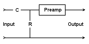
This filter has a "cutoff" frequency of
F = 1 / (2 * pi * R * C).
Any input component at this frequency will have its amplitude reduced by 3 dB (to 70.71%). Higher frequencies are passed (that's why we call it "high-pass") with less amplitude reduction as the frequency rises. Lower frequencies have their amplitudes strongly reduced: For every halving of frequency below the cutoff, the output will be further cut in half.
Let's say you want to build a 300 Hz high-pass filter. You might want something like this to reduce powerline interference (50 or 60 Hz), or to remove DC and low-frequency drift components before a high-gain preamplifier stage. Here's what the frequency response will look like:
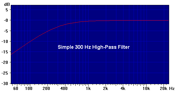
(The above curve was created with the EQ_Curve macro, which disusses the math in more detail. The separate Example Curves and Parameters topic provides the complete cut-and-paste parameter set.)
You probably want to pick R somewhere in the 10000 ohm (10K) to 100000 ohm (100K) range. (Too small may load down the signal source, and too large may encourage the circuit to act like an antenna and pick up 60 Hz power line noise from the surroundings, as well as not allow the preamp to operate properly.) So let's start with 33K, which is the geometric middle of that range. (10K / 33K is about the same as 33K / 100K.) Rearranging our formula we find:
    C = 1 / (2 * pi * R * F)
      = (2 * 3.1415 * 33000 * 300)
      = 1.6 * 10^-8 Farads
        (16 nF, or 0.016 uF)
If you happen to have this value on hand, you are done. However, since resistors are readily available in many more values than capacitors, you may need to use the nearest value of C that you have, then solve for a new value of R.
Note that the input impedance of the preamp is in parallel with the resistor, and will need to be considered unless it is many times larger. Usually, the impedance is either high enough to ignore (over 1 Megohm), or low due to a simple fixed resistance across the input of the circuit.
If you know that this impedance is a simple resistance, you can select your filter resistor such that the parallel combination gives the correct value.
Otherwise, if you only know a general ballpark range for the input impedance, you will probably want to select the filter resistor to be around one tenth of this or less. Then select the capacitor accordingly.
Low-Pass Filter:
Similarly, you can make a low-pass filter to remove unwanted high frequency components:
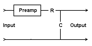
This is just the mirror of the high-pass filter, and it uses the same formula. Here again input signals at the cutoff frequency have their amplitudes reduced by 3 dB, but now higher frequency components are cut in half for every doubling of frequency.
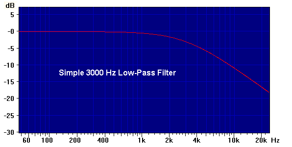
Here's what the frequency response will look like for a 3000 Hz cutoff, as displayed by the EQ_Curve macro using the 1st-Order Low-Pass cut-and-paste parameters from the Example Curves and Parameters:
The formula assumes that the output impedance of the preamp is much lower than the filter resistor, which is usually a safe assumption with modern equipment. Otherwise, its value must be added to the resistor value to get the effective R for the filter calculation.
More importantly, this circuit assumes that the input impedance of whatever follows the output of the filter is much higher than the filter resistor... at least 10 times, and hopefully more. If the signal goes to a sound card input, note that typical impedances are in the 50K range.
Otherwise, there will be two problems: First, the output level of the filter will be reduced due to a voltage divider effect. You can compensate for such losses by adjusting the External Gain factor.
Second, and possibly more serious, the filter cutoff frequency is affected as well. For this purpose, the input impedance resistor acts like it is in parallel with the filter resistor, so the cutoff frequency is increased. You can measure the actual input impedance and include it in your calculation of the filter resistor.
Or, you can use a much smaller filter resistor, subject to the above limitations of the preamp output, such that you can ignore the input impedance by comparison. (Probably 1-2k is a good lower limit.) Then compute a new (larger) capacitor value to go with the smaller resistor.
Alternatively, you can just adjust the R and C values by trial and error (within limits) until you get an acceptable response. For example, if you think the input impedance is about the same size as the filter resistor you calculated, meaning the cutoff frequency is about doubled, you can double the capacitor size and then start adjusting while you watch the response.
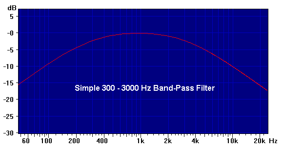
You can easily use both high-pass and low-pass filters on opposite ends of the same preamp, to get a broad band-pass filter. Here's the response of the above 300 Hz high-pass and 3000 Hz low-pass combined:
If these simple filters don't reduce unwanted frequencies enough, there are more elaborate filters available. However, these are not made by just cascading multiple simple filters. Typically these filters would be active filters, which use operational amplifier chips and require operating power. But they are much easier to design and adjust than passive filters, which often require non-standard capacitor and/or inductor values. See the Complex-Pole Filters section under the Example Curves and Parameters topic associated with the EQ_Curve macro mini-app.
There is one potential problem with using filters to reduce noise: They often change the appearance of the waveform, beyond removing the unwanted components. The desired signal will typically have its different frequency components shifted in time by different amounts, so that what started as a sharp pulse or step may become smeared out or even show transient oscillations. More elaborate filters can help this, but these can be expensive to buy or difficult to adjust.
The best solution to preserving the input waveform is often to use synchronous waveform averaging where possible. This powerful technique can extract perfect waveforms that have been completely buried in noise.
- Back to Expnote.DAT Arb File
- Ahead to Formulas For Working With Sound
- Daqarta Help Contents
- Daqarta Help Index
- Daqarta Downloads
- Daqarta Home Page
- Purchase Daqarta
Questions? Comments? Contact us!
We respond to ALL inquiries, typically within 24 hrs.INTERSTELLAR RESEARCH:
Over 35 Years of Innovative Instrumentation
© Copyright 2007 - 2023 by Interstellar Research
All rights reserved