Software for Windows
Science with your Sound Card!


Features:
Oscilloscope
Spectrum Analyzer
8-Channel
Signal Generator
(Absolutely FREE!)
Spectrogram
Pitch Tracker
Pitch-to-MIDI
DaqMusiq Generator
(Free Music... Forever!)
Engine Simulator
LCR Meter
Remote Operation
DC Measurements
True RMS Voltmeter
Sound Level Meter
Frequency Counter
Period
Event
Spectral Event
Temperature
Pressure
MHz Frequencies
Data Logger
Waveform Averager
Histogram
Post-Stimulus Time
Histogram (PSTH)
THD Meter
IMD Meter
Precision Phase Meter
Pulse Meter
Macro System
Multi-Trace Arrays
Trigger Controls
Auto-Calibration
Spectral Peak Track
Spectrum Limit Testing
Direct-to-Disk Recording
Accessibility
Data Logger
Waveform Averager
Histogram
Post-Stimulus Time
Histogram (PSTH)
THD Meter
IMD Meter
Precision Phase Meter
Pulse Meter
Macro System
Multi-Trace Arrays
Trigger Controls
Auto-Calibration
Spectral Peak Track
Spectrum Limit Testing
Direct-to-Disk Recording
Accessibility
Applications:
Frequency response
Distortion measurement
Speech and music
Microphone calibration
Loudspeaker test
Auditory phenomena
Musical instrument tuning
Animal sound
Evoked potentials
Rotating machinery
Automotive
Product test
Contact us about
your application!
Sound Card External DC-to-AC Modulator
Introduction:
Although a standard Windows sound card can not handle DC or very low-frequency inputs, you can add an external circuit that converts them into AC signals it can easily handle. This doesn't require any modification to your existing sound card... you just connect your DC signals to the circuit, and plug the circuit outputs into the normal Line In jack on the card.
The drawback of this approach is that it limits the upper frequency range to a few kHz at best... typically only a few hundred hertz. This is not likely to be an issue for most slow-changing measurements like temperature or pressure.
If you really need high frequency response as well as response down to DC, you will need to modify a sound card. Alternatively, if you only need to measure 0-5V you can use an inexpensive Arduino or Numato board with the DC_Chart_Recorder macro mini-app for slow-speed work, or the DaquinOscope (Arduino only) for high speeds.
The basic concept here is that a DC input signal is switched on and off ("chopped") by a square wave modulator that runs at a frequency the sound card can easily pass, such as 1 kHz. The result is a 1 kHz square wave whose amplitude is the same as the DC input level, and can be measured with the sound card. The exact frequency of the square wave is unimportant, only its amplitude.
This approach will work fine for DC signals that are always positive or always negative, but it can't distinguish one from the other. A square wave that alternates between zero and a positive level will be converted by the sound card's AC coupling into one that is half above and half below zero... exactly the same as if the original switched between zero and a negative level.
To get around this, the Signed Modulator circuit below has four switching states instead of two: A positive reference voltage, then an inverted version of that reference, then the raw input voltage, then the inverted input. This 4-state cycle repeats continuously, with each state lasting 1 msec.
The reference level is chosen to be greater than any valid signal, allowing Daqarta's Decimate Signed option to deduce which phases are which, and thus to infer the correct polarity of the input signal.
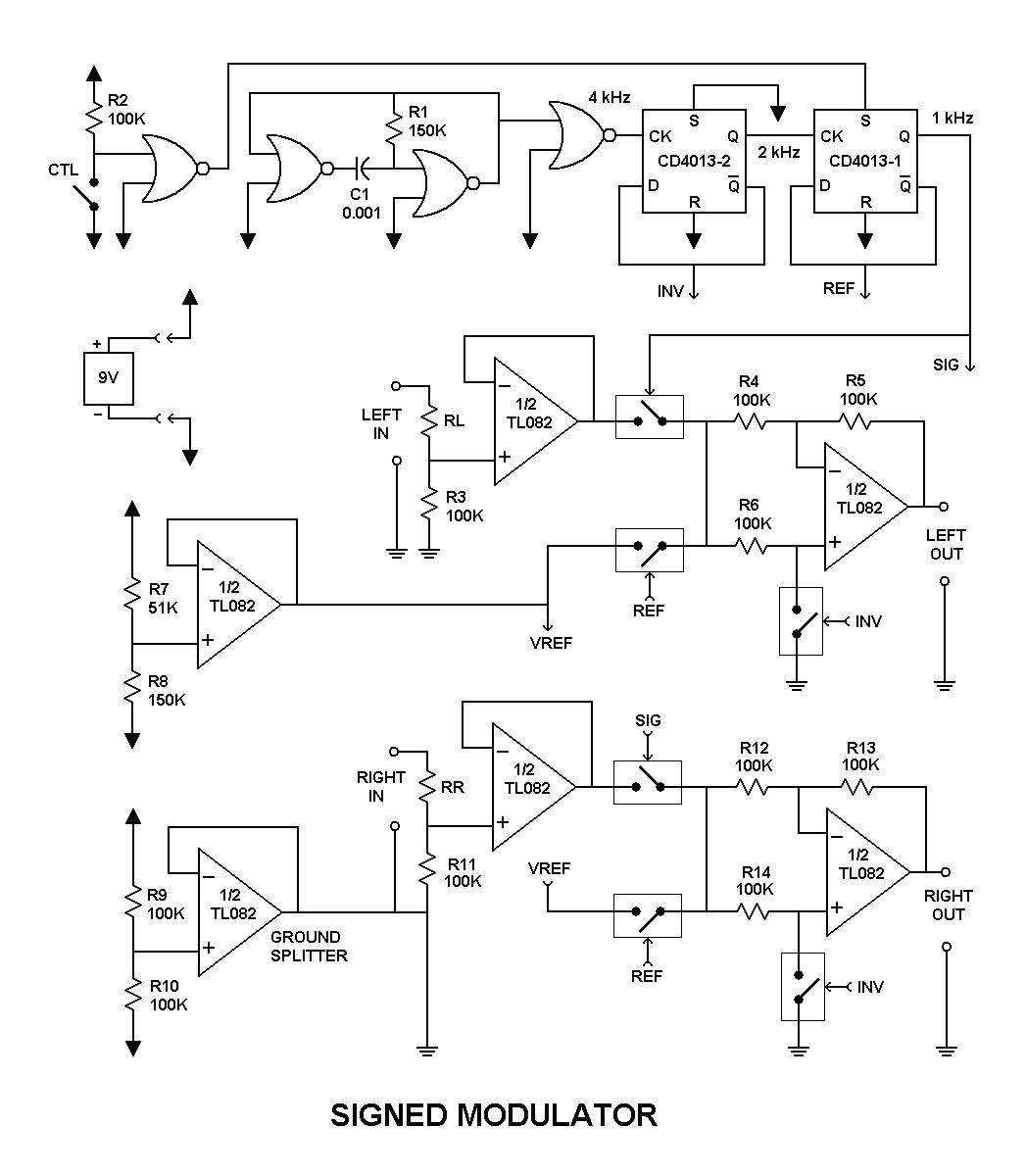
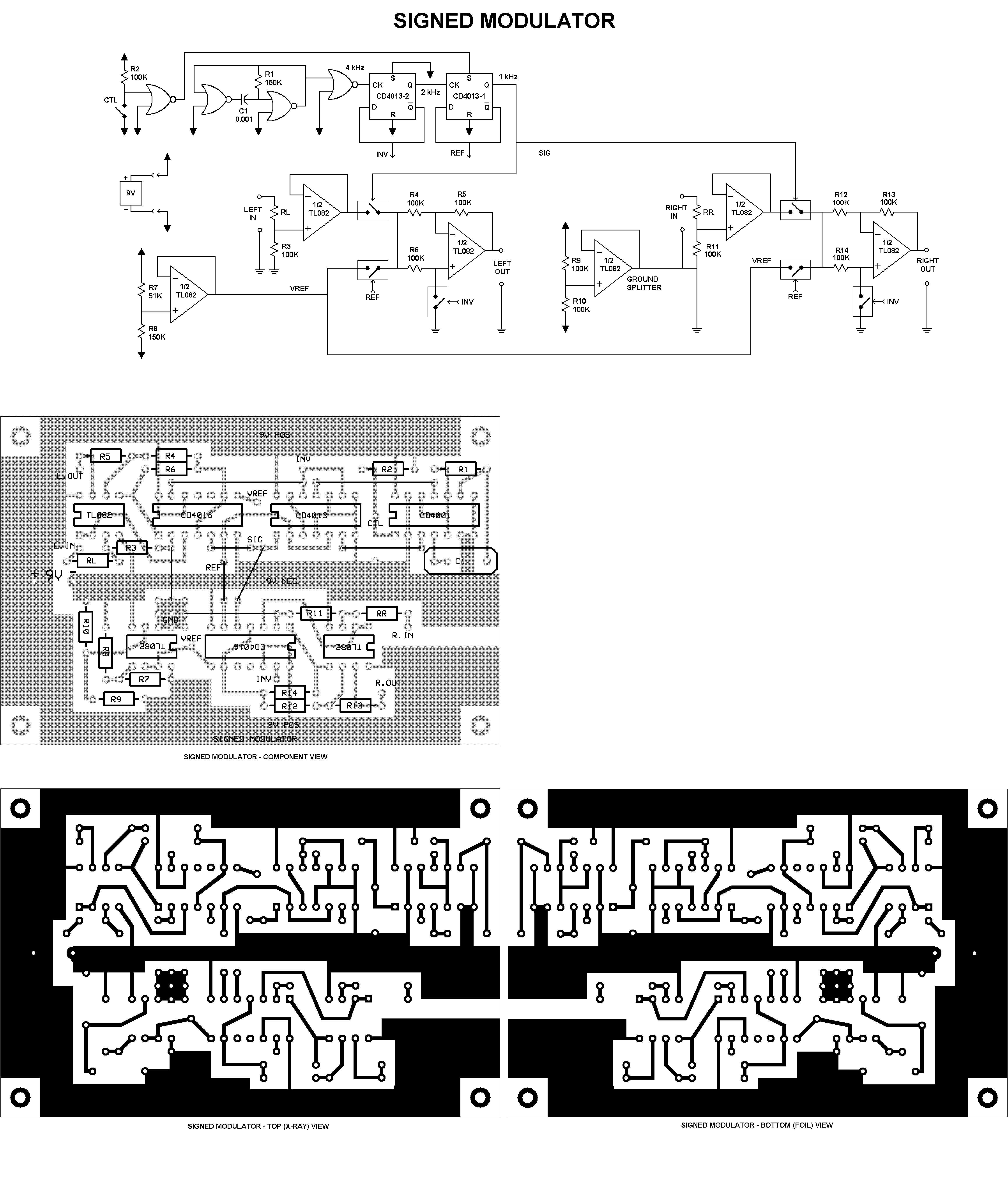
Circuit Details:
The circuit is powered by a 9 V "transistor radio" battery. A "ground splitter" at bottom left uses an op-amp (half of a TL082) that buffers voltage divider R9 and R10 to create a pseudo-ground at half the supply, effectively giving +/-4.5 V supplies for other op-amp stages.
Another TL082 section (middle left) buffers voltage divider R7 and R8 to provide a positive VREF reference voltage at approximately 2.25 V above the pseudo-ground.
At the top, a buffered 4 kHz clock from three NOR gates (CD4001) is divided down by two flip-flop stages (CD4013) to produce a 2 kHz INV output plus complementary 1 kHz REF and SIG outputs that control three analog switches (CD4016) per channel. (The top-left NOR allows an optional unsigned mode of operation... see below.)
First consider the case when INV and SIG are off and REF is on. Looking at the Left channel output stage (middle right), the VREF reference voltage is connected via R6 to the non-inverting input of the op-amp, and also via R4 to the inverting input. (Since SIG is off, VREF is the only input to both.)
Since INV is off, this circuit is applying both inverting and non-inverting gains to VREF at the same time. To analyze this we consider each case separately and then combine. The gain for the non-inverting function is (1 + R5/R4) = (1 + 1) = 2. The inverting gain is -R5/R4 = -1. The net result is a non-inverting gain of 1, so the output is VREF.
Then after 1 msec INV switches on, which shunts the non-inverting input to ground. Now this stage is a simple inverter, so the output is -VREF.
After another 1 msec INV goes back off, and SIG goes on while REF goes off. Now we are back to the non-inverting state, but with SIG instead of VREF going to the output.
Finally, another msec later INV goes on and -SIG goes to the output. This holds for 1 msec, then the whole cycle repeats.
The timing is shown below. Only INV and REF are shown at the top, since SIG is just the inverse of REF. Below the two timing traces are output waveforms for positive and negative input signals (VSIG). Note that these look fundamentally different.
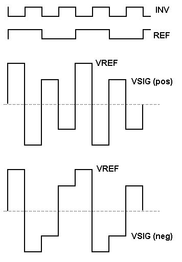
To decipher these waveforms, Daqarta's Decimate Signed option first determines the largest waveform peak and calls that VREF. (This means that the input signal must never get this large in normal operation.) Next, it determines the polarity of the sound card's input channel; if the positive VREF pulse arrives after the negative, the overall channel is inverting the signal, so Daqarta corrects for that.
After the negative VREF level goes off, whatever level comes next is the true input signal, with proper polarity. This is the value that the Signed option reports for the current sample interval. If more than one complete 4-state cycle happens during the sample interval, the individual signal levels from each cycle are averaged together to get the reported sample value.
Note that for proper operation, the overall Decimate Rate must be less than the 1 kHz full-cycle rate. The specific rate is not critical, but likewise the simple oscillator here is subject to component tolerances and drift. Thus, it's best to use a safety factor such as setting Decimate Rate to half the full-cycle rate or less.
The CTL switch at top left in the circuit diagram allows an optional unsigned mode of operation that is suitable for use with the Demodulate option. When the switch is closed, the SIG line stays high and the REF line stays low, so the circuit just switches between normal and inverted input signal at a 2 kHz rate.
The above schematic plus complete 600 DPI board and parts placement layouts suitable for printing are included in the SgnModAll600.PNG file that is installed with Daqarta in the Documents - Daqarta - Circuits folder.
Be sure to read the Notes section of Daqarta Printed Circuits before you begin.
You can use the printed layouts directly to create your own circuit boards, with either the laser printer toner transfer method, or with the direct-draw method discussed under Printed Circuit Construction.
Alternatively, you can edit the SgnMod.PCB file in the same folder to make custom modifications first. See the PCB Files discussion in Daqarta Printed Circuits for the required software to use this file, and for information on how to submit it to have boards made by a 3rd-party supplier.
See also Sound Card DC Input / Output Modification, DC Measurements And Outputs, Decimate Signed
- Back to Sound Card DC Input / Output Modification
- Ahead to Sound Card DC Pulse Output Circuits
- Daqarta Help Contents
- Daqarta Help Index
- Daqarta Downloads
- Daqarta Home Page
- Purchase Daqarta
Questions? Comments? Contact us!
We respond to ALL inquiries, typically within 24 hrs.INTERSTELLAR RESEARCH:
Over 35 Years of Innovative Instrumentation
© Copyright 2007 - 2023 by Interstellar Research
All rights reserved