![[LogoShip]](logo5.png)
Software for Windows
Science with your Sound Card!


Gut-Level Fourier Transforms - Part 4:
Spectral Leakage
Previous Next
In past discussions we saw that a simple sinusoid multiplication method is the heart of Fourier analysis. The same general approach is used in both analog (swept-spectrum) and in digital spectrum analyzers:
- The product of two sinusoids yields components at their sum and difference frequencies.
- An unknown input times a known reference frequency thus has a DC (0 Hz) difference component only for an input component at the reference frequency.
- The DC value can be recovered by a lowpass filter or simple average, whereas all other components are sinusoids that average to zero.
- The DC value is proportional to the amplitude of the input signal at that reference frequency.
- This process can be carried out with as many different reference frequencies as needed to obtain a detailed spectrum.
Digital analyzers apply this process to discrete data sets. The general Discrete Fourier Transform (DFT) can handle sets of arbitrary size, but it is rarely used. Instead, the Fast Fourier Transform (FFT) obtains much greater efficiency by employing power-of-2 sizes. But either way, the simple averaging method used by these digital techniques has a serious shortcoming compared to the lowpass filters used in analog systems. We'll discuss that problem here and next time we'll detail the solution. Although the discussion refers to the FFT, keep in mind that the DFT has the same problem.
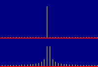
Consider the spectrum of a pure sine wave signal: The FFT should yield a response at a single spectral line, as shown in the upper trace of Figure 1. In reality, however, that only occurs when the input signal happens to fall exactly on a reference frequency. Otherwise, we get something like the lower trace: Instead of a single line, it shows a whole forest of components that are not actually present in the signal.

Fig. 1: Spectra of Inputs On and Between Spectral Lines
This happens whenever an input component falls between the spectral lines (reference frequencies) of the FFT analysis. Granted, we can't expect the analyzer to have infinite resolution. But even if we recognize that the FFT can only show responses at discrete lines, we still might reasonably expect something neater than this... say, responses at only the two nearest lines with heights proportional to where the true frequency falls within the interval between them. So, what are all those other lines, spreading away like skirts around the true location?
They're called spectral leakage. Spectral leakage arises from the fact that the FFT uses a finite analysis time interval, represented by the N samples used in the analysis. As far as the theory is concerned, these N samples constitute exactly one period of an infinite-duration waveform. The analysis assumes that the whole wave can be reconstructed by simply repeating those N samples over and over.
If the N input samples span one period, then repeating them does indeed give an accurate representation of the input waveform. But in the typical case, there is no particular correlation between N and any feature of the input signal, so we usually get some fractional number of cycles.

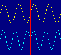
Fig. 2: Repeating Integer and Non-Integer Periods
Figure 2 shows the problem graphically. The left side corresponds to N samples, which are simply repeated to form the right side. The upper trace holds an integer number of sine wave periods in N samples, so when it repeats it appears as a continuous sine. But the lower trace ends midway through a cycle, so when it repeats there is an obvious discontinuity at the splice.
Digital Fourier analysis, whether DFT or FFT, uses the single-period assumption to dutifully (but blindly) compute the spectrum for the specified interval of the data. In the integer case, the spectrum is a single peak corresponding to the frequency of the input wave, which we saw as a vertical line in the upper trace of Figure 1. That's just what we expected for a single-frequency sine input.
But the effective discontinuity of the non-integer case scatters the energy over many sidebands, as we saw in Figure 1's lower trace. In essence, the energy has "leaked" from the single line and spilled over into adjacent lines. That's actually what we would expect, if we fed such a complex waveform into an ideal spectrum analyzer: lots of harmonics of a low-frequency fundamental (the splice repetition rate), with major energy around the original sine frequency.
To see how these leakage lines arise from the simple averaging process of the FFT, consider that the Fourier analysis uses only reference frequencies that are integer multiples of a fundamental, which just fits into the N-sample period. The resultant spectrum will show the response at each of those discrete frequencies. As an example, suppose that we collect N = 1024 samples at a sample rate of 10240 per second: The analysis period is thus 0.10 second, and the spectral lines will be 10 Hz apart, from 0 to 5110 Hz.
Now suppose the input signal is at 1005 Hz, midway between two lines. You might think that the resultant spectrum would simply show lines at 1000 and 1010 Hz, with half the energy in each. But life is not that simple. Recall that the analysis works by multiplying the input by each of the reference frequencies and averaging each product, and that each product consists of sum and difference terms.
When our 1005 Hz input is multiplied by the 1000 Hz reference, we get sum and difference components of 2005 and 5 Hz: There is no DC term. In the 0.10 second represented by our N samples, the 5 Hz component will only go through a half cycle, and the average value of a half-cycle sinusoid works out to be 2/pi or about 0.6366. A similar analysis applies to the 1010 Hz line. So the tallest two lines (as shown in the lower spectrum of Figure 1) are each only about 0.6366 of the true height shown in the single line of the upper spectrum.
(The 2005 Hz component goes through 200.5 cycles in this same 0.10 second; the 200 whole cycles average to zero, but the remaining half is 1/401 of the total and so adds only 0.6366/401 to the value reported at the 1000 Hz line.)
Now consider that the 990 and 1020 Hz references will give difference components of 15 Hz, which are 1.5 cycles of the base period. The full cycle portion will average to zero, but the remaining half cycle is 1/3 of the total and so will give a response of 0.6366/3. This process repeats for reference frequencies farther above and below the input, each having a residual half cycle, but taking up a smaller fraction of the total: 1/5 of 2.5 cycles at a difference of 25 Hz, 1/7 at 35 Hz, and so on.
You can verify this behavior for yourself by spending a little time fooling around with a spectrum analyzer, using simple sine wave inputs. If you don't have such a system, you may want to download the author's Daqarta for Windows software that turns your Windows sound card into a full-fledged spectrum analyzer... and much more.
All Daqarta features are free to use for 30 days or 30 sessions, after which it becomes a freeware signal generator... with full analysis capabilities. (Only the sound card inputs are ignored.)
So how can we get rid of these spectral leakage lines, yet still take advantage of the computational speed of the FFT? The solution is spectral windowing, which we'll cover next time.
Previous Next
Features:
Oscilloscope
Spectrum Analyzer
8-Channel
Signal Generator
(Absolutely FREE!)
Spectrogram
Pitch Tracker
Pitch-to-MIDI
DaqMusiq Generator
(Free Music... Forever!)
Engine Simulator
LCR Meter
Remote Operation
DC Measurements
True RMS Voltmeter
Sound Level Meter
Frequency Counter
Period
Event
Spectral Event
Temperature
Pressure
MHz Frequencies
Data Logger
Waveform Averager
Histogram
Post-Stimulus Time
Histogram (PSTH)
THD Meter
IMD Meter
Precision Phase Meter
Pulse Meter
Macro System
Multi-Trace Arrays
Trigger Controls
Auto-Calibration
Spectral Peak Track
Spectrum Limit Testing
Direct-to-Disk Recording
Accessibility
Data Logger
Waveform Averager
Histogram
Post-Stimulus Time
Histogram (PSTH)
THD Meter
IMD Meter
Precision Phase Meter
Pulse Meter
Macro System
Multi-Trace Arrays
Trigger Controls
Auto-Calibration
Spectral Peak Track
Spectrum Limit Testing
Direct-to-Disk Recording
Accessibility
Applications:
Frequency response
Distortion measurement
Speech and music
Microphone calibration
Loudspeaker test
Auditory phenomena
Musical instrument tuning
Animal sound
Evoked potentials
Rotating machinery
Automotive
Product test
Contact us about
your application!
Questions? Comments? Contact us!
We respond to ALL inquiries, typically within 24 hrs.INTERSTELLAR RESEARCH:
Over 35 Years of Innovative Instrumentation
© Copyright 2007 - 2023 by Interstellar Research
All rights reserved