Software for Windows
Science with your Sound Card!


Features:
Oscilloscope
Spectrum Analyzer
8-Channel
Signal Generator
Spectrogram
Pitch Tracker
Pitch-to-MIDI
DaqMusiq Generator
(Free Music... Forever!)
Engine Simulator
LCR Meter
Remote Operation
DC Measurements
True RMS Voltmeter
Sound Level Meter
Frequency Counter
Period
Event
Spectral Event
Temperature
Pressure
MHz Frequencies
Data Logger
Waveform Averager
Histogram
Post-Stimulus Time
Histogram (PSTH)
THD Meter
IMD Meter
Precision Phase Meter
Pulse Meter
Macro System
Multi-Trace Arrays
Trigger Controls
Auto-Calibration
Spectral Peak Track
Spectrum Limit Testing
Direct-to-Disk Recording
Accessibility
Data Logger
Waveform Averager
Histogram
Post-Stimulus Time
Histogram (PSTH)
THD Meter
IMD Meter
Precision Phase Meter
Pulse Meter
Macro System
Multi-Trace Arrays
Trigger Controls
Auto-Calibration
Spectral Peak Track
Spectrum Limit Testing
Direct-to-Disk Recording
Accessibility
Applications:
Frequency response
Distortion measurement
Speech and music
Microphone calibration
Loudspeaker test
Auditory phenomena
Musical instrument tuning
Animal sound
Evoked potentials
Rotating machinery
Automotive
Product test
Contact us about
your application!
Sound Card Low-Level Distortion Analysis Techniques
Every measurement system has some finite limit on the range of values it can handle.
Consider the needs of a system to measure the distortion of an audio power amplifier. Typical modern amplifiers may have distortion levels (harmonic or intermodulation) that are below the noise floor of your sound card. Even with waveform averaging to reduce the noise in the measurement, you may find that distortion from the sound card itself is larger than anything from the amplifier.
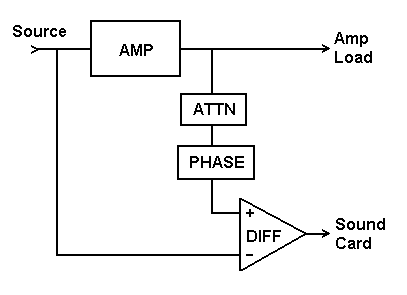
In other words, if you send a high-level stimulus signal to the amplifier (or other low-distortion system) under test, then at its output will appear that same signal (perhaps greatly amplified), plus one or more much-smaller distortion components. If you want to analyze this composite signal with a sound card, you must provide attenuation such that the large stimulus portion will not overload the card's input.
Even at levels below outright overload, the stimulus portion may induce detectable distortion from the sound card. If you reduce the level in order to reduce this added distortion, you will also be reducing the amplifier distortion components you are trying to measure. What is needed is a way to reduce the high-level stimulus portion, while leaving the low-level portion unaffected.
One standard method is to apply a "notch" filter to the signal, carefully adjusted to cut only the stimulus frequency. For measuring intermodulation distortion, you will need a notch filter for each of the stimulus frequencies. Changing to new stimulus frequencies requires re-tuning. Since the notch must be very sharp in order to cut only the stimulus without affecting nearby difference tones, small tuning errors can allow large amounts of stimulus to pass.
A preferred alternative method is to use simple subtraction to remove the stimulus component(s) from the amplifier output signal. This can be done because you have access to both the input and output signals for the amplifier. If you attenuate the output to compensate for the amplifier gain, it should be identical to the input except for any added distortion. You can then subtract them via a simple difference circuit, also known as a "differential amplifier", and obtain the distortion components alone.
If it happens that the amplifier inverts the signal anyway, you could replace the difference circuit with a passive resistive summing network, like the one previously shown for adding two sources to measure intermodulation distortion.
The attenuator can be a simple "volume control" added to the input of the difference circuit. For finer adjustment of the control, use series resistors Ra and Rg to supply the bulk of the attenuation when you know the amplifier gain A.
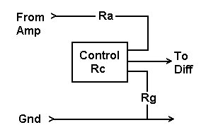
A multiple-turn control will give even finer adjustment. If the control has a total resistance of Rc, select Rg about 10 times as big, then select Ra = Rg * A. For example, suppose the amplifier has a gain A = 20 and the control has Rc = 1K. Then select
Rg = 10 * Rc = 10 * 1K = 10K
Rs = Rg * A = 10K * 20 = 200K
This will allow adjustment for a range of gains from about 19 to 21.
Observe the spectrum of the output from the difference circuit while you adjust the attenuator for a minimum at the stimulus frequency. If there are two stimulus frequencies, both peaks should go down at the same time. Note that the difference stage may be driven into clipping at first, before you find the right adjustment, which will create lots of spurious spectral peaks.
Once the stimulus itself is cancelled, the difference output can be preamplified to drive the ADC for better sensitivity. Consider that if you use the subtractor to null out 48 dB of stimulus (typical, though you can often do even better), you can effectively add that 48 dB to the measurement range of the sound card. That's equivalent to adding another 8 bits to the resolution of your card, not counting what you might gain by waveform averaging!
Note that waveform averaging reduces the noise floor to allow better resolution of low-level components. Spectrum averaging would only show you the average noise level... not helpful here. So start the average in waveform display mode and then toggle Spectrum mode to see the spectrum of the waveform average.
For averaging multiple tones produced by the Daqarta Generator, the Trigger mode should be set to Gen Sync. (Auto and Normal triggering modes look only at slope and level, so would not synchronize to the complex waveform.)
Some amplifiers, especially at high frequencies, may introduce phase shifts that prevent this simple subtraction method from reducing the stimulus to near zero. If it is still big enough to cause sound card distortion, you will need to add a compensating phase shift to your subtraction circuit. You can use simple high-pass or low-pass RC filters with adjustable R (since these produce 90 degree shifts near their cutoff frequencies), as long as you recognize that these are also changing the effective attenuation. Adjustment can be tricky until you get near the desired null point, since you will be adjusting both phase and level controls together.
The phase adjustment could be done at either subtractor input by changing from high-pass to low-pass or vice-versa. Since you typically won't know ahead of time just how much phase shift you need, or in what direction, you must be prepared to switch things around or change capacitor values.
If the phase shift is different for each of the two stimulus tones in an intermodulation test, and you can't get satisfactory results by "splitting the difference" on a single phase adjustment, you will need to use a separate source for each stimulus tone. Combine them directly (using the resistive network previously shown) to drive the amplifier, but provide each with separate phase and level controls before combining to go to the subtractor.
These same techniques will work in many other cases where you need to measure extremely small distortions, such that any sound card would be challenged. The subtraction method will work for any type of distortion measurement, as long as you have access to both the input and output signals of the system under test.
You can measure extremely low levels of distortion with this approach, much lower than the residual distortion present in the stimulus signal itself. That's because the stimulus distortion is also subtracted away, so all you are left with is whatever was added by the device under test. What's more, this method is not limited to simple tone stimuli, or even steady-state conditions. As long as you can adequately control for phase shifts, the stimulus can be a complex or transient signal, even speech or music.
See also Distortion - Theory And Measurement
- Back to Sound Card IMD Meter Mini-App
- Ahead to Creating Low IMD Acoustic Signals via Sound Card
- Daqarta Help Contents
- Daqarta Help Index
- Daqarta Downloads
- Daqarta Home Page
- Donate to Daqarta
Questions? Comments? Contact us!
We respond to ALL inquiries, typically within 24 hrs.INTERSTELLAR RESEARCH:
Over 45 Years of Innovative Instrumentation
© Copyright 2007 - 2026 by Interstellar Research
All rights reserved