Software for Windows
Science with your Sound Card!


Features:
Oscilloscope
Spectrum Analyzer
8-Channel
Signal Generator
Spectrogram
Pitch Tracker
Pitch-to-MIDI
DaqMusiq Generator
(Free Music... Forever!)
Engine Simulator
LCR Meter
Remote Operation
DC Measurements
True RMS Voltmeter
Sound Level Meter
Frequency Counter
Period
Event
Spectral Event
Temperature
Pressure
MHz Frequencies
Data Logger
Waveform Averager
Histogram
Post-Stimulus Time
Histogram (PSTH)
THD Meter
IMD Meter
Precision Phase Meter
Pulse Meter
Macro System
Multi-Trace Arrays
Trigger Controls
Auto-Calibration
Spectral Peak Track
Spectrum Limit Testing
Direct-to-Disk Recording
Accessibility
Data Logger
Waveform Averager
Histogram
Post-Stimulus Time
Histogram (PSTH)
THD Meter
IMD Meter
Precision Phase Meter
Pulse Meter
Macro System
Multi-Trace Arrays
Trigger Controls
Auto-Calibration
Spectral Peak Track
Spectrum Limit Testing
Direct-to-Disk Recording
Accessibility
Applications:
Frequency response
Distortion measurement
Speech and music
Microphone calibration
Loudspeaker test
Auditory phenomena
Musical instrument tuning
Animal sound
Evoked potentials
Rotating machinery
Automotive
Product test
Contact us about
your application!
Full-Scale Range - Output Voltage Method
Controls: Calibration Menu >> Full-Scale Range
Introduction:
This approach to Full-Scale Range calibration involves measuring the Generator output with an external voltmeter and setting the Output Range, then applying the now-calibrated signal to the input to get the Input Range.
Note: You must have previously run Auto-Calibrate for the output and input lines whose range you want to set; otherwise, their controls will be disabled in the Full-Scale Range dialog.
In addition, you should also perform input and output impedance measurements on your card, since these values will be used to correct the calibration.
Finding Output Range:
To measure the output voltage accurately you need a separate voltmeter that has a sensitive AC Volts range, ideally one that can read 3 decimal places (1.999), or at least 2 places (19.99) AC volts full-scale.
Connect the meter to the output. If you are clipping the meter leads to the end of a male-male cable plugged into the output, the red lead goes to the tip (Left channel) and the black lead goes to the shank (common or ground). Don't try to clip onto the little ring between the tip and shank (Right channel), since it's hard to avoid shorting things together. This procedure only uses the Left channel, and Daqarta assumes the Left and Right calibrations are identical.
Set the Generator to produce a sine wave at maximum volume and 100% Level. The frequency should be in the range of 50 to 1000 hertz for best accuracy on most meters. The reading from the meter will be an RMS value, which you must convert to amplitude by multiplying by 1.4142 (the square root of 2). Enter that value for Wave Out in the Range dialog.
Alternatively, you can skip the RMS-to-amplitude conversion and compare the Daqarta Voltmeter RMS reading with the external meter RMS reading. You might want to do this if you are tweaking a prior calibration, or especially if you want to run the output at a softer volume because it distorts at the maximum setting (see below). Note that you can use lower volumes only because you have done a relative calibration with Auto-Calibrate.
Just open the Daqarta Voltmeter (ALT+V) and set the channel to Left Out and the mode to RMS. The true Wave Out range will then be the current Wave Out range (default 1.000) times the external meter reading divided by the Daqarta Voltmeter reading, both in RMS volts.
True_Range = Current_Range * V_Ext / V_Daqarta
Finding Input Range:
Now Daqarta has become a calibrated signal generator which you can use as a reference signal source to calibrate the inputs. Use a "loopback" connection (as in Auto-Calibrate) to connect the outputs to the inputs. In the Input dialog make sure both Left and Right channels are active. Select Line In and set the Line In level to 0.
Adjust the output volume until you get a large (nearly full-scale) input, without over-driving it into distortion. One easy way to do this is to monitor the spectrum instead of the waveform; when you drive the input too hard, you will see a sudden onset or rise of spectral peaks at harmonic frequencies. This is much more sensitive than judging sine-wave distortion by viewing the waveform.
It is unfortunately all too common for sound card inputs to distort well before the input signal reaches full-scale... sometimes as little as half-scale.
Now set the Daqarta Voltmeter to Left In and read the RMS voltage. Since Daqarta is assuming whatever Input Range value is currently set (default 1.000 volt), this "apparent" voltage is unlikely to be the true input voltage... yet.
Now read the signal level that produces that input voltage by toggling the Daqarta Voltmeter from Left In to Left Out. To find the true full-scale input range, multiply the current Range by the output voltage divided by the apparent input voltage.
Test_RangeIn = Current_RangeIn * Vout / Vin
For example, suppose the true output is 250 mV where the apparent input is 0.600 volt with the default full-scale range of 1.000 volt. Then the correct full-scale value will be:
1.000 * 0.250 / 0.600 = 0.4167
However, the above calculation does not consider the sound card output and input impedances. The situation is a voltage divider that reduces the true input voltage Vi at the sound card's ADC, relative to the true no-load sound card output Vo:
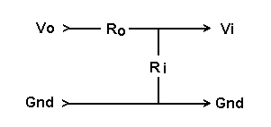
The value calculated above assumed output impedance Ro was zero. The true value has been reduced by the divider according to:
Ri / (Ro + Ri)
So to find the correct value, which we would have gotten if the assumptions were true, we multiply the computed value by the reciprocal of the above:
True_RangeIn = Test_RangeIn * (Ro + Ri) / Ri
Enter the True_RangeIn value as the Stereo Range value for that Input line.
Double that value and enter it for Mono. That's the value Daqarta will use when only the Left or Right Input channel is selected; it will be OK for most cards, since they sum the two inputs together in that case. But note that if you have separate Left and Right Input level controls, each will be applied to its respective channel, even though one channel is apparently not selected.
This makes Mono calibration very tricky to use. It's much better to always use both channels, even if you have no signal applied to one of them.
See also Full-Scale Range Dialog, Full-Scale Range - DaquinOscope Method Input Voltage Method, Polarity Determination, Calibration Menu
- Back to Full-Scale Range Dialog
- Ahead to Full-Scale Range - DaquinOscope Method
- Daqarta Help Contents
- Daqarta Help Index
- Daqarta Downloads
- Daqarta Home Page
- Donate to Daqarta
Questions? Comments? Contact us!
We respond to ALL inquiries, typically within 24 hrs.INTERSTELLAR RESEARCH:
Over 45 Years of Innovative Instrumentation
© Copyright 2007 - 2026 by Interstellar Research
All rights reserved