Software for Windows
Science with your Sound Card!


Features:
Oscilloscope
Spectrum Analyzer
8-Channel
Signal Generator
Spectrogram
Pitch Tracker
Pitch-to-MIDI
DaqMusiq Generator
(Free Music... Forever!)
Engine Simulator
LCR Meter
Remote Operation
DC Measurements
True RMS Voltmeter
Sound Level Meter
Frequency Counter
Period
Event
Spectral Event
Temperature
Pressure
MHz Frequencies
Data Logger
Waveform Averager
Histogram
Post-Stimulus Time
Histogram (PSTH)
THD Meter
IMD Meter
Precision Phase Meter
Pulse Meter
Macro System
Multi-Trace Arrays
Trigger Controls
Auto-Calibration
Spectral Peak Track
Spectrum Limit Testing
Direct-to-Disk Recording
Accessibility
Data Logger
Waveform Averager
Histogram
Post-Stimulus Time
Histogram (PSTH)
THD Meter
IMD Meter
Precision Phase Meter
Pulse Meter
Macro System
Multi-Trace Arrays
Trigger Controls
Auto-Calibration
Spectral Peak Track
Spectrum Limit Testing
Direct-to-Disk Recording
Accessibility
Applications:
Frequency response
Distortion measurement
Speech and music
Microphone calibration
Loudspeaker test
Auditory phenomena
Musical instrument tuning
Animal sound
Evoked potentials
Rotating machinery
Automotive
Product test
Contact us about
your application!
Sound Card LCR Meter Mini-App with ESR, DF, and Q
![[LCR Meter (45K image)]](LCR_Mtr.png)
- Introduction
- Credit
- Theory
- Test Fixture
- Initial Set-Up
- Calibration
- Operation
- LCR_Meter Macro Listing
- _LCR_Ctrls Macro Listing
- _LCR_Task Macro Listing
Introduction:
The LCR_Meter macro mini-app included with Daqarta allows measurement of inductance (L), capacitance (C), and resistance (R), including Equivalent Series Resistance (ESR) of capacitors. Optionally, it can also show capacitor Dissipation Factor DF or inductor Q.
No external circuitry is needed, just a passive test fixture (which can be as simple as clip leads). Only a single known resistance value is needed for calibration, typically a 1K resistor measured with a DMM of the desired accuracy.
You can run LCR_Meter by hitting the F8 key followed by the 'Z' key, or hitting CTRL+F8 to open the Macro Dialog and double-clicking on LCR_Meter in the Macro List.
LCR_Meter uses a Custom Controls dialog that allows calibration and control of various parameters. You can open this Help topic by right-clicking anywhere in the dialog, or on the meter display.
The meter shows a resistance value, plus a capacitance or inductance value. Values are auto-scaled in engineering units: 'Ohm', 'K', or 'M' for resistance, 'pF', 'nF', or 'uF' for capacitance, or 'uH', 'mH', or 'H' for inductance.
By default, the displayed values assume that the resistance is in series with the capacitance or inductance, so the ESR can be read directly from the resistance value. For small-valued capacitors (or for ordinary resistors), you can toggle to the equivalent parallel values. Instead of ESR, the display will then show the equivalent leakage resistance of a capacitor.
You can save meter measurements to a log file with a single button click, including a separate user entry for the marked component value (or another identifier). You can also save extended notes, or headers for log file sections, via a second button.
Basic accuracy for all measurements is determined by a single reference resistor, typically around 1000 ohms; no capacitors or inductors are needed for calibration. The specific value of the resistor is unimportant, as long as it is accurately known. You don't need to purchase a precision resistor if you have access to a decent multimeter to measure whatever resistor you use; even an under-$10 hand-held 3 1/2 digit meter will give better than 1% accuracy.
Note: See Arduino_RCtime Multi-Pin Resistance/Capacitance Meter for monitoring up to 6 different resistance or capacitance values simultaneously.
Credit:
Special thanks to Robert A. Macy for the original inspiration for this project, as well as technical advice and support.
Theory:
The LCR_Meter works by sending a sine wave test signal through a known resistance, and measuring the complex (real and imaginary) voltage across that resistance to obtain the current through it. That current is then passed through the component under test, and the complex voltage across the component is measured. Knowing the current and voltage, the complex impedance can be calculated.
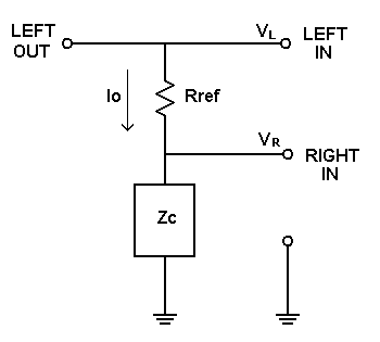
Assuming for the moment that the sound card inputs have infinite impedance, the voltage across Rref is the difference Vl - Vr between the Left and Right inputs, where both Vl and Vr are complex values of the form R + jX. The complex current Io through Rref is then:
Io = (Vl - Vr) / Rref.
If the Right input has infinite impedance, then Io must also flow through the complex impedance Zc of the component under test. Knowing the current Io and voltage Vr, we can find Zc via Ohm's law:
Zc = Vr / Io
However, this simplified circuit model is not accurate enough for our purposes. There are three main shortcomings that we must address:
1) The sound card inputs do not have infinite impedance, and are typically more like 15K or even less.
2) The ground path shown in the above diagram actually includes some cable impedance Zg in series with Zc.
3) Although the sound card inputs should have the same gain, the match isn't necessarily good enough for precision measurements.
The following diagram includes the Right input impedance Zr and the ground impedance Zg:
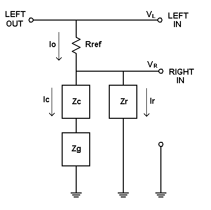
The reference current Io is now split between component current Ic and Right input current Ir. The system must be calibrated to account for this, as well as ground impedance and gain differences. See the Calibration section, below.
Test Fixture:
In order to use the LCR_Meter you will need a test fixture to hold the reference resistor and the component being tested. It must allow shorting either of these as needed for calibration, and provide cable connections to the sound card output and inputs. Here's a basic schematic:
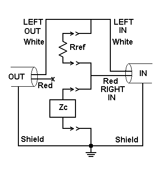
A simple solution is to use a small piece of perfboard with two "mini-alligator" or similar clips mounted for the reference resistor and two for the component. With this arrangement, you'll need to remove the reference to replace it with a short for calibration.
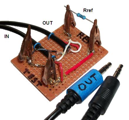
The photo shows copper-plated clips (which happened to be on hand), but the standard "chrome"-looking (bright nickel or cadmium plating) may be better. These are "toothless" clips, but standard teeth would be fine.
The clips are held to the perfboard with copper-plated nails (5/8 x 17 coppered weatherstrip nails), but you could use 5/8 x 16 brass-plated linoleum nails or any similar small solderable nail. Drill out perfboard to just fit the 4 nails; driving them through is likely to crack standard perfboard. Push each nail up from the bottom, then crimp the clip onto it. It doesn't need to be a tight grip, since you will be soldering later.
You'll also need cables to connect the fixture to the sound card output and input jacks. These should generally be kept as short as possible, typically one foot or less. But don't despair if you need longer cables, such as to reach from the rear of a desktop system to your work surface; longer cables typically still give good readings for the "ideal" component values (resistance of a resistor, capacitance of a capacitor, or inductance of an inductor), but show more error and noise in the other term. For example, with 1-foot cables a 1 Megohm resistor might show several pF of parallel capacitance, while an added 6-foot extension may change this to several Henries, even after re-calbration.
You can purchase a short male-male stereo computer audio cable and cut it in two, using one end for the output and the other for the inputs.
Strip the outer insulation and expose the twisted or braided sheath that serves as the common ground for both channels. Peel that back to expose the white (Left channel) and red (Right) conductors. Do this for both cables.
For the cable that will connect to the sound card inputs, strip both the red and white wires. For the output cable strip only the white wire; leave the red wire unconnected, and insulate it with shrink tubing or otherwise protect it from shorting to anything.
Strap the cables to the perfboard to provide strain relief. You can make simple straps from hookup wire which loops over the cable's outer insulation and through the perfboard. Twist the ends as needed to draw the cable tight to the board. Do this in two places on each cable, at least a half inch apart. (These are blue in the above photo.)
Twist the shields of the two cables together and solder to the ground clip. This is the bottom Zc clip in the schematic, which is the left "TEST" clip in the photo. You may need to need to add a hookup-wire extension (black and white wire in the photo) to reach the clip. Due to the mass of the clip and nail, may want to use a hot soldering iron or gun and apply liquid rosin flux to the clip-nail-wire junction before soldering. Also, make sure the clip is properly oriented, and that the clip and nail head grip the board tightly.
Solder both white wires to the top clip for Rref as shown in the photo and schematic. Again, be sure to get a proper alignment and a good grip.
The remaining two clips should be connected together with hookup wire (red in the photo) to form the junction between the bottom of Rref and the top of Zc as shown in the schematic. Solder the red input wire to either clip, again making sure both clips are aligned and grip well.
Important: Mark the plug that will connect to the output jack, using a piece of tape or a conspicuous dab of paint. The other plug will, of course, go the input jack. By marking only one, you can tell at a glance which is which, without having to read any labels.
The above fixture will be awkward to use with some components, or for in-circuit testing. You can extend the "TEST" clips with clip leads, making sure that you have those leads in place for the calibration. The LCR_Meter is very tolerant of this; 20-inch clip leads still give accurate readings, even testing a 47 pF capacitor.
Simple Alternative Fixtures:
You can make a "quick-and-dirty" fixture from a section of solderless breadboard. You'll need to solder hookup wire to the ground leads so they can be inserted into the board contacts. Tin the Left and Right conductors lightly with solder so they will be stiff enough to push in. This "fixture" will only work for components that can be inserted into the breadboard, but it may be more convenient than the clip-type fixture above if you want to test a lot of parts with leads that are already formed for insertion.
Also, you can cut a mini-gator clip lead and tin the ends, allowing you to clip to larger components or perform in-circuit tests.
Another alternative is to omit the fixture entirely, and just solder the cut ends of clip leads directly to the cables, insulating with shrink tubing or even electrical tape in a pinch. You can solder the reference resistor in place, or use short clip lead ends.
Initial Set-Up:
Before you can make measurements with the LCR_Meter you need to perform a one-time set-up of the output level, input line selection, and input levels.
Connect your test fixture to the sound card output and input jacks. Start LCR_Meter by hitting the F8 key followed by the 'Z' key, or hitting CTRL+F8 and double-clicking on LCR_Meter in the Macro List.
Use a short circuit instead of the reference resistor.
Open the Input control dialog and make sure Line is selected, and also insure that both Left and Right channels are active.
Now you need to adjust the output and input levels to get the largest signal that doesn't clip. Start by setting the Line Levels and/or Master Levels (depending on your system) to 0 (maximum sensitivity). If the waveform shows signs of clipping, reduce those levels (more negative) as needed to eliminate it. Toggle to Spectrum display mode and observe the harmonic peaks relative to the main signal peak at 1031.25 Hz. You should reduce the levels until the harmonics drop suddenly; they might still be present (depending on your sound card), but they should be much smaller. (This Spectrum method is a much more sensitive test of clipping than observing the waveform.)
Some systems have separate Left and Right input levels; be sure to adjust both to the same value.
If you don't see any signs of clipping even with the Input levels at 0, then maybe the output level can be increased. Alternatively, if you do see clipping that can't be reduced via the Input levels, then the output level must be decreased. Hit the F9 key to open the output Volume/dB Slider dialog, and adjust those controls as needed. You may have to juggle back and forth a bit between input and output controls for best results. Some cards have output distortion only at the highest slider ranges on Master or Wave only, but not interchangeably: You have to reduce the proper slider, even though either one reduces the signal level.
Once you have found the best settings, you need to insure that you use them on future LCR_Meter sessions. If you changed the output volume, save the LCRmeter.GEN setup using the Save Setup button near the bottom of the Generator dialog. That Generator setup, complete with output level settings, is loaded automatically when LCR_Meter starts up.
However, there is no corresponding "setup" file that you can save for input level settings. The current settings are always saved at the end of a Daqarta session, and restored at the start of the next. That takes care of changes to the input levels that might be caused by other software, but it doesn't help if you want to use different input settings for different Daqarta applications.
The best way to insure that the input levels are always correct for LCR_Meter is to set them directly in the macro itself. InVolL and InVolR set the Left and Right Line Levels, while InMstL and InMstR set the Master Levels (if present). Example commands are commented out via leading semicolons in the LCR_Meter macro listing, which you can edit by selecting LCR_Meter and hitting the Edit button in the Macro List dialog.
    ;InVolL=-150
    ;InVolR=-150
    ;InMstL=0
    ;InMstR=0
Replace the -150 values in this example with the values you just determined, then remove the semicolons from those two lines. Leave the Master lines commented out unless your card actually has those controls, in which case set your values. Conversely, if your card has only Master controls, leave the InVolL and InVolR lines commented out and update the Master lines instead.
Save the changed LCR_Meter macro by clicking the Save Macro button at the bottom of the Edit dialog. Then save the entire Daqarta0.MAC macro file for future sessions via the Save File button at the bottom of the main Macro List dialog.
Calibration:
The first time you use LCR_Meter you must enter the actual Reference Resistor value in the control at the upper right. The accuracy of this value sets the baseline accuracy for all measurements. You can use a precision resistor, or measure a standard resistor with a multimeter having the desired accuracy. Precision wirewound resistors are ideal, but not really needed; an ordinary metal film resistor is a good choice. (Carbon film is usable but somewhat less stable, and carbon composition is least stable.)
The value you enter for Reference Resistor will be saved as user variable VarR. This value is retained across Daqarta sessions, so you won't need to enter it again unless some other macro uses it in the meantime. If you want to guard against that, you can enter the value on the second line of the LCR_Meter macro (currently commented out with a leading semicolon in the listing, below).
The following description refers to the circuit diagrams in the Theory section above. Note that during calibration you will be monitoring the meter values only to see that they are settling, ignoring the actual readings. This usually only takes a few seconds per step. Don't worry if they don't settle perfectly; you just don't want to end the calibration step while the readings are still trending in a constant direction.
With no component present, apply a short-circuit across the reference resistor Rref so that the same Left output signal goes to both Left and Right inputs. Then toggle the Calibrate - Ref SHORT button on; wait for a few seconds until the meter readings stabilize, then toggle the button off. Remove the short.
While shorted, LCR_Meter measures the two voltages and determines their ratio; when the button is toggled off, the ratio is saved. This will later be used to correct the Right input voltage Vr before subtracting from the Left input Vl to find the voltage across Rref.
Next, still with no component present, toggle the Calibrate - Test OPEN button on for a few seconds while LCR_Meter measures the Right input impedance Zr, and toggle it back off when the meter readings are stable. The impedance is measured using the original circuit model, except that Zr takes the place of Zc as the only current path.
Later, when a component is being measured, the complex current Ic through the component is needed in order to find its impedance via Zc = Vr / Ic. But Ic is equal to the known current Io through the reference resistor, minus the current Ir through the Right input impedance. Ir is thus found via Ir = Vr / Zr, where Vr is the same voltage across both the component and the input impedance.
The final calibration step is to apply a short in place of the component, so only the ground resistance Zg is present in the component path. Toggle the Calibrate - Test SHORT button on for a few seconds, until the meter values stabilize, then toggle it off before remvoving the short. During the shorted calibration interval, LCR_Meter measures Zg and saves the complex values for later subtraction from the total measured impedance when Zc is present.
Note that in each calibration step, the relevant short or open condition must remain in place until the corresponding button is toggled off.
Operation:
Perform the above calibration each time you start LCR_Meter.
To measure a component, insert it in the Zc position. If the reading is too noisy, toggle the Averager button on. Use the button in the LCR_Meter dialog, not the one at the left end of the main Daqarta toolbar. (The dialog button forces the needed waveform average, even from Spectrum display mode.)
Noise Reduction:
You can increase the averager time constant to further reduce noise, although settling time will increase as well. Make sure you are in waveform display mode (Spectrum and Sgram/PT toolbar buttons both toggled off) and open the Waveform Averager dialog (thin unmarked button below the toolbar Averager button). Then increase the Frames Request setting from the default of 32. Two doublings of the request (eg to 128) give half the noise; don't bother with changes of less than a doubling.
If you prefer, you can modify the LCR_Meter macro to use a different default. Just change the WavgFrames=32 line as desired.
Series versus Parallel Mode:
By default, LCR_Meter shows series equivalent values. These assume the component is a series connection of the two values shown on the meter. That's usually reasonable for most inductors, or for large capacitors. But real-world resistors are unlikely to have much series inductance, and no series capacitance, so you may want to toggle the button at the lower right from 'Show SERIES' to 'Show PARALLEL'. A resistor which shows microfarads of series capacitance will show picofarads of parallel capacitance... much more plausible.
You'll also want 'Show PARALLEL' for small capacitors, which will otherwise show very large series resistance. The parallel equivalent would be leakage resistance, and it will be much larger still. For example, a typical 47 pF capacitor might show a series resistance of 100K, but the parallel equivalent would be over 10 Megohms.
In most cases, the "ideal" component values (resistance of a resistor, capacitance of a capacitor, or inductance of an inductor) will be correct, or very close, regardless of whether you use the series or parallel equivalents. The main use of the series / parallel button is for interpretation of non-ideals like capacitor leakage or series resistance.
Saving Data or Notes to the Log File:
Clicking on the Save Data to Log File button will save the current meter readings to the next line in the Daqarta log file. The line will start with the current local time, followed by the contents of Field1 (below the Value label), followed by 'S' for Series or 'P' for Parallel mode (see above), followed by the resistance and reactance values, including units. Here is a typical entry, where '47 pF' was entered into Field1 at the start of the test:
09:49:42.203 47 pF P 22.707 M 46.812 pF
Clicking on the Save Notes to Log File button will start a new line and save the entire contents of the Daqarta Notes area to the log file. You can use this to enter longer descriptions than will fit into Field1. Typically, you might enter a description of the test series about to be measured, such as "Ceramic Disc Capacitors" with the current date and any other relevant data. (You can enter the date via CTRL+ALT+D.)
Then for each part you'd enter its component value or part number in Field1 before measuring it and hitting Save Data to Log File.
Dissipation Factor DF and Q:
Dissipation Factor (DF) is the ratio of the resistance over the reactance for a capacitor. For an inductor, the corresponding value is Q, which is the reciprocal of DF. (Note that this is component Q, which is not the same as Q for a resonant circuit.)
By default, LCR_Meter doesn't show these. To enable them change the first line of the LCR_Meter macro from UD=0 to UD=1.
If the measured component has a negative (capacitive) reactance, the meter will display a third value labeled DF.
If the reactance is positive (inductive), the third value will be Q.
Likewise, when saving data to the log file, the relevant DF or Q value will be appended after the reactance value, and labeled as above.
Noise and Drift Effects:
Note that noise and drift can have a curious effect due to the way capacitance and inductance are computed from the measured reactance X (the imaginary part of the complex impedance R + jX). If X is positive, it is inductive with a value given by:
L = X / (2 * pi * ToneFreq)
If X is negative, it is capacitive:
C = -1 / (2 * pi * ToneFreq * X)
Now consider what happens when X is near zero. A very small positive X gives a very small inductance value, but a very small negative X gives an enormous capacitance value due to X being in the denominator. So a tiny drift that causes X to wander above and below zero can cause the reported reactance to flip from a few uH to millions of uF. If you encounter this, try re-running the calibration procedures to account for drift-related changes in the sound card component values. Some systems may benefit from starting LCR_Meter and just letting it run for a few minutes of warm-up before performing the calibration.
Reference Frequency:
The default test frequency is 1031.25 Hz, which is synchronous with the default sound card sample rate of 48000 Hz, and with Daqarta's 1024-sample data frames. In each frame of 1024 samples, there is an exact integer number N cycles of the test frequency: N = 1024 * 1031.25 / 48000 = 22. That means that no spectral window function is needed, since the test frequency and all its harmonics fall exactly on the spectral lines of the FFT. More importantly, it allows the GenSync Trigger Mode to insure that every frame starts on the identical phase of the test waveform. This reduces noise and jitter in measurements.
If you change the Reference Frequency control, LCR_Meter will choose the nearest frequency that maintains this integer relationship. If you must use another frequency (say, to adhere to a mandated test spec), toggle the 'Spectral Line Lock ON' button to 'Arbitrary Frequency' before changing the frequency. In this case the Spectrum Window type specified in the Spectrum control dialog will be applied automatically by LCR_Meter, even if the Window button is not toggled on in the dialog. The Hann window type is set by LCR_Meter as the default.
Note that even in Arbitrary Frequency mode there are still certain frequencies that allow every frame to start on the same phase. These are frequencies that are exactly divisible into the sample rate. For example, 1000 Hz meets this criterion at the default sample rate of 48000 Hz.
Alternatively, there are Spectral Line Lock frequencies which are also integers. At 48000 Hz sample rate, these are all multiples of 375 Hz, such as 375, 750, 1500, 3000, 6000, and 12000.
The default test frequency is good for sorting unmarked parts, and for general audio work. Higher frequencies may be needed for special applications; you can raise the sample rate to the limits of your card's capabilities, making sure that the test frequency you select is well under half of that (the Nyquist limit).
However, if you use very high test frequencies there are more likely to be problems with parasitic capacitance and inductance in the test setup. Try to use short connecting cables, and keep your body away from the test fixture during measurements. (It can be hard to do both on a laptop, if the audio connectors are near the keyboard.)
A USB sound card can make it easier to use short audio cables. The USB cable carries only digitized data, so its length doesn't affect the LCR_Meter. By essentially moving the whole sound card closer to the test location, you may be able to use very short audio cables between the USB device and the test connectors.
Reference Resistor:
Using a reference resistor in the 1000 ohm range (at the default Reference Frequency) will allow resistor measurements from less than one ohm to more than one Megohm, or capacitors from 10 pF to over 100 uF, or inductors from 10 uH to several H.
The LCR_Meter measuring circuit is essentially a voltage divider, with the reference resistor on top and the test component on the bottom. When the component resistance or reactance is low, the voltage being measured is likewise low and thus more likely to give noisy readings. This may be a problem for capacitors much larger than 100 uF.
You can increase the measured voltage by using a smaller reference resistor. Using 100 ohms will make the measured voltage about 10 times larger, reducing the noise by a corresponding factor. However, this is less effective on cards with high output impedance on Line Out, such as the Behringer UCA202 with over 400 ohms. The Headphone Out on this card is only 51 ohms, which is much better.
Going down to a 10 ohm reference should improve things by yet another factor of ten, but this only works on cards with low output impedance and adequate drive so that they don't distort under such a heavy current demand.
Conversely, raising the reference resistor to 10K should allow measurements above 10 Megohms, and, in principle, 100K should go above 100 Megohms. However, since sound cards typically have input impedances of around 15K (or even less), measurement accuracy is critically dependent upon the calibration procedure being able to cancel out the input impedance.
It turns out that Rref = 10K seems to work fairly well for resistances up to 10 Meg, as verified by a Fluke 8050A bench-type meter. (It also reads a nominal 22 M resistor, but the Fluke stops at 20 M so it can't be verified.)
With a 100K reference, 10 M could still be read properly, but a 100 M carbon composition resistor read only about 40 M. With no way to verify, it could be a correct reading due to surface contaminants on the resistor... or it could be that this was just beyond the limits of the calibration scheme to compensate.
If you really need to work in the area above 1 Megohm, you might consider building an op-amp buffer for the Right In channel. This will boost the input impedance beyond 10 Megohms, which hopefully can be easily cancelled by the calibration procedure.
In-Circuit Testing:
Note that sound card inputs share the common ground of the computer; they are not isolated. To measure component values in an external circuit, make sure it is disconnected from mains power and is not grounded anywhere else (such as through cables to other equipment).
As a precaution, you can run LCR_Meter on a laptop that is running on battery, and has all printers and other possibly-grounded external devices disconnected.
For in-circuit testing, the applied voltages should be well below 0.5 V peak to avoid activating diode or transistor junctions.
The LCR_Meter uses AC test voltages, typically +/-2 V or less open-circuit. Since the test circuit is a voltage divider such that the reference resistor is in series with the component under test, the actual applied test voltage may be much less than the open-circuit voltage.
For in-circuit testing of electrolytic capacitors, the Equivalent Series Resistance (ESR) will typically be low enough to bring the applied voltage down to the range of a few millivolts.
However, if you are testing high-impedance circuits, you may want to reduce the output voltage. Use the F9 key to open the output volume control sliders after starting the LCR_Meter, but before calibrating it or connecting to the circuit. Observe the input waveforms, and adjust the sliders for a circuit-safe voltage. Then calibrate and measure as usual. Note that reducing the voltage in this way will mean increased measurement noise, so you may need to increase the Waveform Averager time constant (the Frames Request).
Electrolytic Capacitor Polarity:
This is usually a non-issue since, as noted above, the ESR of the capacitor itself will pull down the test voltage to millivolt levels.
LCR_Meter Macro Listing:
;<Help=H4910
UD=0                           ;No DF or Q display
;VarR=1000                  ;Reference resistor (use actual value)
Close=                     ;Close any open data file
Spect=0
Sgram=0
Trig=1
TrigMode=GenSync
A.LoadGEN="LCRmeter"
ZeroUnits=0
SpectWindOn=1              ;No Window (default)
SpectWind=0                ;Hann Window when active
E.IF.WaveMute=             ;No Mute on Vista or later
    WaveMute=0
ENDIF.
E.IF.MasterMute=
    MasterMute=0
ENDIF.
InL=1
InR=1
Input=1
;InVolL=-150                        ;See Initial Set-Up, above
;InVolR=-150
;InMstL=0                           ;Only if Master Input Levels
;InMstR=0                           ; present on your sound card
WavgMode=Exp
WavgFrames=32

Label1="Value"

Ctrls="<<LCR Meter Controls"

Ctrl0="<<Reference Frequency"
Ctrl0="<S(SmplRate/1024,SmplRate*511/1024)"
F=1031.25                  ;Default test freq (synchronous)
Ctrl0=F
L.0.ToneFreq=F             ;Set test freq for Left Out

Ctrl1="<< Reference Resistor"
Ctrl1="<E(9,1M5)"
IF.VarR=0                  ;Actual value set in 1st line?
    Ctrl1=1000             ;If not, default to 1000
    VarR=1000
ELSE.
    Ctrl1=VarR             ;Else set actual value
ENDIF.

Ctrl2="<X"                 ;Unused controls
Ctrl3="<X"

Btn0="Spectral Line Lock ON"
Btn0="<T"
Btn0=1
Fstep=Dir

Btn1="Calibrate - Ref SHORT"
Btn1="<T"
Btn1=0

Btn2="Averager"
Btn2="<T"
Btn2=0

Btn3="Calibrate - Test OPEN"
Btn3="<T"
Btn3=0

Btn4="Save Data to Log File"
Btn4="<M"
UF=0

Btn5="Calibrate - Test SHORT"
Btn5="<T"
Btn5=0

Btn6="Save Notes to Log File"
Btn6="<M"

Btn7="Show SERIES"
Btn7="<T"
Btn7=0

Mtr0="<<LCR Meter - SERIES Equivalents"
Mtr0="<C(0)"               ;Black text
Mtr0="<B(hFFFFFF)"         ;White backround
Mtr0="<H4910"

Buf6[900]#a=" pF"          ;Capacitance units
Buf6[901]#a=" nF"          ;(string element)
Buf6[902]#a=" uF"

Buf6[903]#a=" uH"          ;Inductance units
Buf6[904]#a=" mH"
Buf6[905]#a=" H"

Buf6[906]#a=" Ohm"         ;Resistance units
Buf6[907]#a=" K"
Buf6[908]#a=" M"

Buf6[910]#a="S"            ;Series code (for Log File)
Buf6[911]#a="P"            ;Parallel code

UC=0                       ;Default capacitance unit = pF
UL=0                       ;Default inductance unit = uH
UR=0                       ;Default resistance unit = Ohm

LO.Disp=0                  ;Don't show output channel
Task="_LCR_Task"           ;Install Task
@_LCR_Ctrls=Ctrls          ;Ctrls active until user close
Task="-_LCR_Task"          ;Remove Task when Ctrls closed
Avg=0                      ;Averager off
Mtr0=                      ;Remove meter
LI.Disp=1                  ;Restore channel displays (if off)
RI.Disp=1
LO.Disp=1
Gen=0                      ;Generator off
Input=0                    ;Inputs off
_LCR_Ctrls Macro Listing:
;<Help=H4910
IF.Ctrls=0                     ;Ctrl0, Ref Freq
    S=SmplRate?X / 1024        ;Spectral Line step size
    IF.Btn0=1                  ;Spectral Line Lock?
        IF.Ctrl0?u=!0      ;Up/Dn scroll?  Next/prior step if so
            L.0.ToneFreq=cint(L.0.ToneFreq / S + Ctrl0?u) * S
        ELSE.
            L.0.ToneFreq=cint(Ctrl0 / S) * S   ;Nearest step
        ENDIF.
    ELSE.                      ;Arbitrary Frequency
        L.0.ToneFreq=Ctrl0     ;Accept entry as-is
    ENDIF.
    F=L.0.ToneFreq         ;New freq
    IF.F=<S                    ;Below min freq?
        F=S                        ;Min = step if so
        L.0.ToneFreq=F             ;Set new freq
    ENDIF.
    Ctrl0=F                    ;Ctrl to new freq
ENDIF.

IF.Ctrls=h80                    ;Ctrl0, Ref Freq slider
    S=SmplRate?X / 1024         ;Line step size
    IF.Ctrl0=<S                 ;Below min?
        Ctrl0=S                     ;Set min = step
        L.0.ToneFreq=S
    ENDIF.
ENDIF.

IF.Ctrls=1                    ;Ctrl1 = Ref R
    VarR=Ctrl1
ENDIF.

;Ctrl2 not used
;Ctrl3 not used

IF.Ctrls=4                    ;Btn0
    IF.Btn0=1
        Btn0="Spectral Line Lock ON"
        S=SmplRate?X / 1024        ;Line step size
        IF.Ctrl0=<S                ;Freq too low?
            Ctrl0=S                ;Set min = step if so
        ENDIF.
        L.0.ToneFreq=cint(Ctrl0 / S) * S   ;Nearest line freq
        Ctrl0=L.0.ToneFreq         ;Set Ctrl to new freq
    ELSE.
        Btn0="Arbitrary Freqency"
    ENDIF.
ENDIF.

IF.Ctrls=5                 ;Btn1 = Calibrate - Ref SHORT
    IF.Btn1=1              ;Button active now?
        Btn2=1                 ;If so, set Averager on
        Avg#W=1
        Btn2="<D"              ;Disable other buttons
        Btn3="<D"
        Btn5="<D"
    ELSE.                  ;Else inactive
        Btn2=0                 ;Averager off
        Avg=0
        Btn2="<N"              ;Enable other buttons
        Btn3="<N"
        Btn5="<N"
    ENDIF.
ENDIF.

IF.Ctrls=6                 ;Btn2 = Averager on/off
    IF.Btn2=0              ;Button off now?
        Avg=0                  ;Averager off if so
    ELSE.
        Avg#W=1                ;Else averager on
    ENDIF.
ENDIF.

IF.Ctrls=7                 ;Btn3 = Calibrate - Test OPEN
    IF.Btn3=1              ;Button active now?
        Btn2=1                 ;If so, set Averager on
        Avg#W=1
        Btn1="<D"              ;Disable other buttons
        Btn2="<D"
        Btn5="<D"
    ELSE.                  ;Else inactive
        Btn2=0                 ;Averager off
        Avg=0
        Btn1="<N"              ;Enable other buttons
        Btn2="<N"
        Btn5="<N"
    ENDIF.
ENDIF.

IF.Ctrls=8                 ;Btn4 = Save Data to Log File
    UF=1                       ;Flag = save on next Task
ENDIF.

IF.Ctrls=9                 ;Btn5 = Calibrate - Test SHORT
    IF.Btn5=1              ;Button active now?
        Btn2=1                 ;If so, set Averager on
        Avg#W=1
        Btn1="<D"              ;Disable other buttons
        Btn2="<D"
        Btn3="<D"
    ELSE.                  ;Else inactive
        Btn2=0                 ;Averager off
        Avg=0
        Btn1="<N"              ;Enable other buttons
        Btn2="<N"
        Btn3="<N"
    ENDIF.
ENDIF.

IF.Ctrls=10            ;Btn6 = Save Notes to Log File
    LogTxt=n + Notes
ENDIF.

IF.Ctrls=11            ;Btn7 = Show as Series / Parallel
    IF.Btn7=0
        Btn7="Show SERIES"
        Mtr0="<<LCR Meter - SERIES Equivalents"
    ELSE.
        Btn7="Show PARALLEL"
        Mtr0="<<LCR Meter - PARALLEL Equivalents"
    ENDIF.
ENDIF.
_LCR_Task Macro Listing:
;<Help=H4910
IF.Avg=0                   ;Averager off?
    Buf0="<=W0"                ;Get raw Ref wave
    Buf1="<=W1"                ;Raw signal wave
ELSE.                      ;Else Avg on
    Buf0="<=a0"                ;Get avg Ref wave
    Buf1="<=a1"                ;Avg signal wave
ENDIF.
Buf0="<*(65536)"           ;Scale up for FFT
Buf1="<*(65536)"
IF.SpectWindOn=1           ;Use spectral window?
    Buf0="<FB0"                ;Windowed Ref FFT
    Buf1="<FB1"                ;Windowed signal FFT
ELSE.                      ;Else no window
    Buf0="<fB0"                ;Unwindowed Ref FFT
    Buf1="<fB1"                ;Unwindowed signal FFT
ENDIF.
Buf2="<mB0"                ;Magnitude spectrum of Ref
UP=pkb(2)                  ;Find peak value in Buf2
UP=Posn?p                  ;Index of peak
A=Buf0[2*UP]               ;Ref peak real component
B=Buf0[2*UP+1]             ;Ref peak imaginary component
C=Buf1[2*UP]               ;Signal peak real
D=Buf1[2*UP+1]             ;Signal peak imaginary

IF.Btn1=1                  ;Calibrate - Ref SHORT?
    VarC=A / C                 ;Ref/Sig gain ratio
ELSE.                      ;Normal run
    C=C * VarC                 ;Apply gain correction
    D=D * VarC
ENDIF.

A=(A - C) / VarR           ;Re of total current Io
B=(B - D) / VarR           ;Im of Io

IF.Btn3=1                  ;Calibrate - Test OPEN?
    H=A^2 + B^2                    ;Denom of Zin = Vc / Io
    VarE=((A * C) + (B * D)) / H   ;Re of Zin
    VarI=((A * D) - (B * C)) / H   ;Im of Zin
    R=VarE                         ;Copy for cal display
    X=VarI
ELSE.                      ;Else normal run
    H=VarE^2 + VarI^2
    A=A - ((VarE * C) + (VarI * D)) / H     ;Re of Io - Iin
    B=B - ((VarE * D) - (VarI * C)) / H     ;Im of Io - Iin
    H=A^2 + B^2                 ;Denom of Zc = Vc / (Io - Iin)
    R=((A * C) + (B * D)) / H   ;Re of Zc
    X=((B * C) - (A * D)) / H   ;Im of Zc
ENDIF.

IF.Btn5=1                  ;Calibrate - Test SHORT?
    VarG=R                     ;Re of ground voltage drop Vg
    VarH=X                     ;Im of Vg
ELSE.                      ;Else normal run
    R=R - VarG                 ;Deduct ground drop
    X=X - VarH
ENDIF.

D=(R/X)^2                  ;Dissipation factor (squared)

;Convert reactance X to capacitance or inductance, auto-scaled:
IF.X=<0                    ;Capacitive reactance (neg Im)?
    L=0                        ;No inductance
    C=-1 / (2 * pi * L.0.ToneFreq * X)     ;Series capacitance
    IF.Btn7=1                  ;Show Parallel?
        C=C / (1 + D)              ;Convert to parallel
    ENDIF.
    C=C * 1M                   ;Scale Farads to microfarads
    IF.C=0                     ;Select auto-scale units
        Uc=2
    ELSE.
        Uc=2 + log10(C) / 3
    ENDIF.
    IF.Uc=>2.2
        Uc=2.2
    ENDIF.
    IF.Uc=>UC + 1.1
        UC=int(Uc)
    ENDIF.
    IF.Uc=<UC
        UC=int(Uc)
    ENDIF.
    C=C * 10^(3 * (2 - UC))    ;Scaled capacitance
ELSE.                      ;Else inductive reactance (pos)
    C=0                        ;No capacitance
    L=X / (2 * pi * L.0.ToneFreq)      ;Series inductance
    IF.Btn7=1                  ;Show Parallel?
        L=L*(1 + D)                ;Convert to parallel
    ENDIF.
    Ui=2 + log10(L) / 3        ;Select auto-scale units
    IF.Ui=>2.2
        Ui=2.2
    ENDIF.
    IF.Ui=>UL + 1.1
        UL=int(Ui)
    ENDIF.
    IF.Ui=<UL
        UL=int(Ui)
    ENDIF.
    L=L * 10^(3 * (2 - UL))    ;Scaled inductance
ENDIF.

;Get resistance R in auto-scaled units
IF.Btn7=1                      ;Show parallel?
    R=R * (1 + 1/D)            ;Convert to parallel
ENDIF.
IF.abs(R)=0                    ;Select auto-scale units
    Ur=0
ELSE.
    Ur=log10(abs(R)) / 3
ENDIF.
IF.Ur=>2.2
    Ur=2.2
ENDIF.
IF.Ur=>UR + 1.1
    UR=int(Ur)
ENDIF.
IF.Ur=<UR
    UR=int(Ur)
ENDIF.
R=R / 10^(3*UR)                ;Scaled resistance

D=sqrt(D)                      ;Dissipation Factor DF

IF.X=<0                        ;Show capacitance?
    IF.UD=0                        ;Don't show DF?
        Mtr0=R + Buf6[906+UR](a) +n + C + Buf6[900+UC](a)
    ELSE.                          ;Show DF
        Mtr0=R + Buf6[906+UR](a) +n + C + Buf6[900+UC](a)_
        +n + D + " DF"
    ENDIF.
ELSE.                          ;Else show inductance
    IF.UD=0                        ;Don't show Q?
        Mtr0=R + Buf6[906+UR](a) +n + L + Buf6[903+UL](a)
    ELSE.                          ;Show Q
        Q=1 / D
        Mtr0=R + Buf6[906+UR](a) +n + L + Buf6[903+UL](a)_
        +n + Q + " Q"
    ENDIF.
ENDIF.

IF.UF=1                        ;Log File request?
    LogTxt=n + t + p16 + Field1 + p33 +Buf6[910+Btn7](a)_
        + p36 + R + Buf6[906+UR](a)
    IF.X=<0
        LogTxt=p52 + C + Buf6[900+UC](a)
        IF.UD=>0                   ;Append DF?
            LogTxt=p70 + D + " DF"
        ENDIF.
    ELSE.
        LogTxt=p52 + L + Buf6[903+UL](a)
        IF.UD=>0                   ;Append Q?
            LogTxt=p70 + Q + " Q"
        ENDIF.
    ENDIF.
    UF=0
ENDIF.
See also Macro Examples and Mini-Apps,
Precision Phase Meter/Plotter/Logger Mini-App,
Arduino_RCtime Multi-Pin Resistance/Capacitance Meter
![]()
- Back to Jitter_Tbl Macro
- Ahead to Sound Card Chart Recorder Mini-App
- Daqarta Help Contents
- Daqarta Help Index
- Daqarta Downloads
- Daqarta Home Page
- Donate to Daqarta
Questions? Comments? Contact us!
We respond to ALL inquiries, typically within 24 hrs.INTERSTELLAR RESEARCH:
Over 45 Years of Innovative Instrumentation
© Copyright 2007 - 2026 by Interstellar Research
All rights reserved