Software for Windows
Science with your Sound Card!


Features:
Oscilloscope
Spectrum Analyzer
8-Channel
Signal Generator
Spectrogram
Pitch Tracker
Pitch-to-MIDI
DaqMusiq Generator
(Free Music... Forever!)
Engine Simulator
LCR Meter
Remote Operation
DC Measurements
True RMS Voltmeter
Sound Level Meter
Frequency Counter
Period
Event
Spectral Event
Temperature
Pressure
MHz Frequencies
Data Logger
Waveform Averager
Histogram
Post-Stimulus Time
Histogram (PSTH)
THD Meter
IMD Meter
Precision Phase Meter
Pulse Meter
Macro System
Multi-Trace Arrays
Trigger Controls
Auto-Calibration
Spectral Peak Track
Spectrum Limit Testing
Direct-to-Disk Recording
Accessibility
Data Logger
Waveform Averager
Histogram
Post-Stimulus Time
Histogram (PSTH)
THD Meter
IMD Meter
Precision Phase Meter
Pulse Meter
Macro System
Multi-Trace Arrays
Trigger Controls
Auto-Calibration
Spectral Peak Track
Spectrum Limit Testing
Direct-to-Disk Recording
Accessibility
Applications:
Frequency response
Distortion measurement
Speech and music
Microphone calibration
Loudspeaker test
Auditory phenomena
Musical instrument tuning
Animal sound
Evoked potentials
Rotating machinery
Automotive
Product test
Contact us about
your application!
Sound Card Cables and Connectors
Stereo Cables and Connectors:
Standard sound cards have 3.5 mm stereo input and output jacks. Cables with 3.5 mm stereo plugs are readily available and quite inexpensive, as are adapter cables with RCA connectors on one end.
Avoid trying to add a 3.5 mm connector to a cable. These are very difficult to solder, and usually cost as much as a complete cable with connectors already attached at both ends.
If you need to connect to equipment with another type of connector, and no ready-made adapter cable can be found, your best bet is probably to buy a long cable with 3.5 mm plugs on both ends. Cut it in half, strip the cut ends as needed, and attach your chosen connectors.
However, many connectors may be difficult to attach to computer audio cables. In such cases, you can make a small adapter box or panel and install the panel-mount style of your chosen connector. Solder the cable ends directly to the back side of this connector, with the cable shield and/or ground soldered to a separate lug under the connector if needed.
Before you solder the cable, thread it through a hole in the adapter box. Make sure you use a grommet to avoid subsequent damage to the cable during use. Tie a loose knot in the cable to act as a strain relief and to prevent it from slipping back through the hole, leaving an adequate length inside the box to allow connections to be made.
The loose knot will prevent the cable from pulling out of the box, but will not protect it against twisting that could pull on the solder joints. Use a tie-wrap to anchor the cable securely to something else inside the box, or use a blob of hot-glue or silicone sealer to anchor the knot securely at the hole.
USB Cable and Connector Pinouts:
USB cables and connectors come in two different types: Type A is for connection to the computer (or smartphone, etc). Type B is for connection to a peripheral device such as a printer or USB sound card, or an Arduino or Numato board.
You may want to know the pinouts and cable colors if you are replacing the loose-fitting mini-USB socket on the 5.1 Channel CM6206 USB card, as discussed in USB Socket Replacement under Sound Card DC Input / Output Modification, as well as the "CAUTION" section of the 5.1 Channel CM6206 USB discussion under Sound Card Performance Tests. (See also the CAUTION below.)
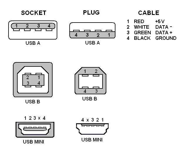
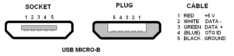
Alternatively, you can use the +5 volt and ground pins of a standard USB port to supply modest amounts of power (100 mA max current draw). This may be used to power small external circuits such as DC Pulse Output Converters.
The simplest approach is to cut up an old USB cable. If you are just using the DC power connections, this can be an old USB 1.0 cable, such as from an old printer or other unused device. Cut off the device connector, and keep the USB connector plus as much cable as you want to connect power to your circuit. Strip the cut end of the cable, then check that the red and black wires do in fact carry +5 and ground, respectively.
CAUTION: Do not rely on the cable colors being correct! The author has personally encountered a USB cable that came with a CM6206 sound card, and had red and black reversed. It had functioned correctly because both ends were reversed; only when cut and tested was it found that +5 was black and ground was red.
Be sure to strap the cable securely to your circuit, or otherwise provide strain relief.
- Back to Dither Demonstration
- Ahead to Sound Card Calibration (.CAL and .FRD) Files
- Daqarta Help Contents
- Daqarta Help Index
- Daqarta Downloads
- Daqarta Home Page
- Donate to Daqarta
Questions? Comments? Contact us!
We respond to ALL inquiries, typically within 24 hrs.INTERSTELLAR RESEARCH:
Over 45 Years of Innovative Instrumentation
© Copyright 2007 - 2026 by Interstellar Research
All rights reserved