Software for Windows
Science with your Sound Card!


Features:
Oscilloscope
Spectrum Analyzer
8-Channel
Signal Generator
Spectrogram
Pitch Tracker
Pitch-to-MIDI
DaqMusiq Generator
(Free Music... Forever!)
Engine Simulator
LCR Meter
Remote Operation
DC Measurements
True RMS Voltmeter
Sound Level Meter
Frequency Counter
Period
Event
Spectral Event
Temperature
Pressure
MHz Frequencies
Data Logger
Waveform Averager
Histogram
Post-Stimulus Time
Histogram (PSTH)
THD Meter
IMD Meter
Precision Phase Meter
Pulse Meter
Macro System
Multi-Trace Arrays
Trigger Controls
Auto-Calibration
Spectral Peak Track
Spectrum Limit Testing
Direct-to-Disk Recording
Accessibility
Data Logger
Waveform Averager
Histogram
Post-Stimulus Time
Histogram (PSTH)
THD Meter
IMD Meter
Precision Phase Meter
Pulse Meter
Macro System
Multi-Trace Arrays
Trigger Controls
Auto-Calibration
Spectral Peak Track
Spectrum Limit Testing
Direct-to-Disk Recording
Accessibility
Applications:
Frequency response
Distortion measurement
Speech and music
Microphone calibration
Loudspeaker test
Auditory phenomena
Musical instrument tuning
Animal sound
Evoked potentials
Rotating machinery
Automotive
Product test
Contact us about
your application!
Sound Card Temperature To Frequency
- Introduction
- Circuit Details
- Calibration
- Single-Point Calibration
- Printable Schematic and Layouts
- PCB File
Introduction:
This circuit allows temperature to be read directly by the Daqarta Frequency Counter using the Fcal option. If you load the LinearC.TBL file as the Fcal Calibration Table, then the Fcal Units button will allow you to toggle the display between degrees Celsius and Fahrenheit, with C or F shown after the display value.
Alternatively, with minor modifications the same basic circuit can be used to read any positive-only voltage, or the output of a positive-only sensor value such as absolute pressure. (For bipolar sensor values such as relative pressure, see the Bipolar Voltage To Frequency circuit.)
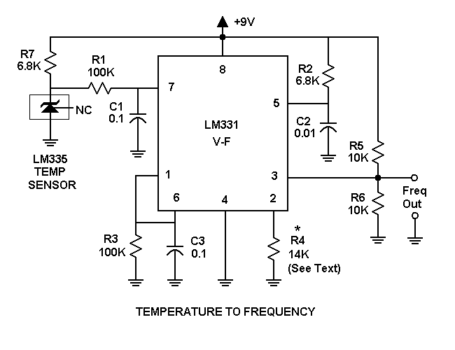
Circuit Details:
This is just the standard voltage-to-frequency circuit from the LM331 datasheet, with the addition of an LM335 precision temperature sensor at the input. It has been designed to run from a single 9 V "transistor radio" battery.
The LM335 delivers a voltage proportional to absolute temperature in degrees Kelvin, with a factor of 10 mV per degree above absolute zero. At the freezing point of water (273 Kelvin or 0 Celsius) this gives 2.73 V.
You don't need to use precision parts or trimmers, since you can calibrate this circuit using the Fcal High and Low controls to compensate. However, you may want to use high stability parts to avoid drift problems in critical applications. For general use, mylar capacitors and 1/4 watt metal film resistors will probably be adequate.
The LM331 datasheet says that for a given voltage V7 at pin 7 the output frequency F is:
F = V7 * R4 / N
Where N = (2.09 * R3 * R2 * C2)
For R3 = 100K, R2 = 6.8K and C2 = 0.01 microfarad, we find N = 14.212. If R4 = 14212 ohms, then the output frequency will be 1000 Hz per volt.
Note that the output is a stream of rectangular high-to-low pulses. The pulse width T is given by:
T = 1.1 * R2 * C2
For the R2 and C2 values given, this is about 75 microseconds. The maximum frequency of operation is limited to a period of about twice this, or 1 / 150 microseconds = 6.7 kHz.
If you are going to use this circuit to measure positive voltages instead of temperature, omit the LM335 and R7, and apply the input voltage to R1 at the point marked "IN" on the component placement layout.
Although designed and tested for the LM335 temperature sensor, other 3-terminal sensors can be used instead. Unlike the LM335, which is powered through R7 and whose output is taken from the same point, most other sensors use a separate power pin... typically the one marked 'NC' (No Connection) here.
To use one of these sensors, omit R7 and connect the positive supply directly to the 'NC' pin. An unused pad has been provided in the layouts for this purpose. Note that some sensors can not handle 9 V power, so you may need to use a separate 5 V power supply. The LM331 will work fine with that.
Also note that different sensors may have different output ranges and characteristics. For example, where the LM335 is 10 mV per degree Kelvin and operates down to -40 C, the LM34 is 10 mV per degree Fahrenheit and can only operate down to +5 F without an added negative supply. The LM61 is 10 mV per degree Celsius, with an offset of 600 mV that allows operation down to -30 C. The LM35 and TMP35 are 10 mV per degree Celsius, but are limited to +10 C and above. The LM36 and TMP36 are also 10 mV per degree C, but have an offset of 500 mV which allows operation down to -40 C. The TMP37 is 20 mV per degree C, and operates down to +5 C.
Provided the range and supply voltage meet your needs, any of these sensors can work in the circuit shown, with differences accommodated via the Fcal High and Low settings.
The above schematic plus complete 600 DPI board and parts placement layouts suitable for printing are included in the TempToFreqAll600.PNG file that is installed with Daqarta in the Documents - Daqarta - Circuits folder.
Be sure to read the Notes section of Daqarta Printed Circuits before you begin.
You can use the printed layouts directly to create your own circuit boards, with either the laser printer toner transfer method, or with the direct-draw method discussed under Printed Circuit Construction.
Alternatively, you can edit the TempToFreq.pcb file in the same folder to make custom modifications first. See the PCB Files discussion in Daqarta Printed Circuits for the required software to use this file, and for information on how to submit it to have boards made by a 3rd-party supplier. See the
Note that in the component placement layout the total R4 value is shown as series resistors R4A and R4B. This allows you to combine values to get closer to the computed value for R4.
You don't really need to do that if you are going to calibrate with known temperatures like an ice bath and boiling water, or if you are using this to measure positive-only voltages and can calibrate with known values. You can use a single standard value like 13K or 15K here, and bend the leads to be 0.5 inch apart instead of the standard 0.4 inch. Then insert it just below the R4A position and it will reach ground without needing a separate jumper.
Otherwise, if you are willing to accept the default calibration of the LM335 (typically within 3 degrees), or you are going to use this circuit in some non-Daqarta application where you can't calibrate it in software, you may want to adjust R4. You can install 13K as R4A, and temporarily install a variable resistor or substitution box for R4B. Without the LM335 or R7, apply a known voltage to R1 at the "IN" point. Monitor the output frequency and adjust for 1000 Hz times the known voltage. Then measure the R4B value and select the nearest standard resistance value.
For remote readings, there are two approaches: You may mount the LM335 remotely and run wires (twisted pair, etc.) to carry the voltage back to the circuit board, or you may locate the entire board remotely and run wires to carry the frequency output back to the sound card inputs.
With the remote sensor approach, the LM335 datasheet notes that for a 1 C error, wire should be limited to 400 feet at 24 wire gage, up to 4000 feet at 14 gage.
Note that mounting the sensor remotely, even if only a foot or so, allows for much easier calibration because you can immerse it into a water bath of known temperature. (See below under "Calibration".)
The remote board approach may have an advantage if the wires must pass through a noisy environment, since they will be carrying a relatively large rectangular pulse signal that will most likely be unaffected by noise. However, keep in mind the eventual need to replace the battery.
Calibration:
For best temperature calibration, you should calibrate at two points, such as in boiling water and an ice bath. Or, if you have a reference thermometer, you can use hot and cold water baths into which you immerse the LM335 and the reference thermometer. (But see Single-Point Calibration, below.)
This is difficult (if not impossible) to do with the sensor mounted on the circuit board. Even if the circuit is intended for ambient temperature measurement, you may want to mount the LM335 on a short cable (say, 2-3 feet) just to aid in calibration. You can tack-solder it temporarily and later re-mount it to the board.
Otherwise, for ambient temperature use you can use a separate reference thermometer that is placed near the LM335 on the board. To get the two temperatures, you can use room temperature for the higher, and the inside of a refrigerator or freezer for the lower. Most household refrigerators have a soft seal that can accommodate the wires from the circuit to the sound card. If the reference thermometer is self-contained (conventional glass, for example) you will have to open the door to read it, but that should be fine as long as you read it quickly.
With whichever scheme you use for the higher calibration temperature, enter the known temperature in degrees Celsius into Fcal High Set and conclude the entry with CTRL+Enter to set Fcal High Raw to the current value.
Similarly, use the lower calibration temperature to set Fcal Low Set and conclude with CTRL+Enter to set Fcal Low Raw.
Now click on Calibration Table in the Fcal dialog and select the LinearC.TBL file. This table is just a one-to-one "conversion", but it has 'Unit:DegC' set to enable the Fcal Units button. The button label will change to 'Celsius', and when you toggle it on it will become 'Fahrenheit'. The Frequency Counter display will show 'C' or 'F' after the value to tell you which is active.
Alternatively, you can enter both Set values in degrees Fahrenheit, and load LinearF.TBL to get the same results.
For use as a positive-only voltage monitor (absolute pressure sensor, etc), use the same general procedure but apply known voltages or sensor conditions to set Fcal High and Low.
Single-Point Calibration:
For non-critical work, you can simplify calibration by assuming that the circuit is linear through zero. Then you can just apply a single reference value or temperature for Fcal High Set.
However, you still need to set Fcal Low. If you are working directly in degrees Kelvin for Fcal High, just set Fcal Low Set and Low Raw to zero. (Don't use CTRL+Enter here, since the Low condition isn't actually present.)
You can also set both Low values to zero if you are using some other sensor that is linear through zero.
However, if you are using the LM335 temperature sensor (or equivalent) that produces an output proportional to absolute temperature and you want to work in degrees Celsius or Fahrenheit, you have to set Low Set to the equivalent absolute zero value, which is -273 Celsius or -460 Fahrenheit. Set Low Raw to zero manually.
See also Fcal Circuits, Printed Circuit Construction, Fcal Dialog, Frequency Counter
- Back to Sound Card Bipolar Voltage To Frequency
- Ahead to Sound Card Thermocouple To Frequency
- Daqarta Help Contents
- Daqarta Help Index
- Daqarta Downloads
- Daqarta Home Page
- Donate to Daqarta
Questions? Comments? Contact us!
We respond to ALL inquiries, typically within 24 hrs.INTERSTELLAR RESEARCH:
Over 45 Years of Innovative Instrumentation
© Copyright 2007 - 2026 by Interstellar Research
All rights reserved