![[LogoShip]](logo5.png)
Software for Windows
Science with your Sound Card!


Gut-Level Fourier Transforms - Part 1:
Everything You Need, You Got in High School
Previous Next
Maybe you learned "all about" Fourier Transforms in college. Your professors did lots of tricks with exponentials and imaginary numbers to conjure up "compact" and "elegant" notations. Do those actually help you understand how real-world spectrum analyzers work? Could you build one, if your life depended on it?
It turns out that spectral analysis is a whole lot simpler than the professors let on. Of course, they had to use those complex numbers, since those are essential to "proper academic rigor". But if your rigor has turned to rigor mortis, perhaps its time for a more intuitive refresher.
This gut-level approach will focus on what really happens inside a spectrum analyzer. It won't use any more math than you probably got in high school, but neither will it omit any details. This is the straight stuff, just looked at from a more down-to-earth point of view.
The key to the whole works is just one equation, usually taught in high school trigonometry... and then discarded by most of us. It's the formula that tells how to multiply two sines together:
Of course, in high school this wasn't very useful. Back when you first saw this, the sines referred to simple angles. But the formula works just as well with sine waves instead... after all, they are just rotating angles.
So the formula tells us that if we have two sine waves (pure tones) at frequencies A and B, when we multiply them together those tones vanish and are replaced by two new tones at the sum and difference frequencies.
For example, if the two original tones are 392 Hz and 440 Hz (keys G and A above "middle C" on a piano), their product gives a difference tone of 48 Hz, and a sum tone of 832 Hz.
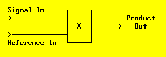
How do we use this for spectral analysis? Suppose we have a multiplier "black box" that we can feed two signals into. One input will be a pure sine wave reference whose frequency we can control, while the other will be the unknown signal we want to analyze. What happens at the output?

Fig. 1: Input Signal Times Reference Sine
In general, we get a whole mess of different output frequencies, since each input signal component will be multiplied separately by the reference and produce its own sum and difference frequencies.
Well, if the input signal had a whole mess of frequencies in it to begin with, how does it help to replace them with a sums-and-differences mess? This is progress?
The trick is what we do with the output of the multiplier. Suppose we just feed it to a simple R-C lowpass filter to find the average DC value. Since sinusoids have equal energy in their positive and negative portions, their average value is zero. So all those sum and difference frequencies will be filtered away to nothing, since they are just a bunch of sinusoids. Right?
Almost right. Consider that any input signal component whose frequency is exactly the same as the reference will have a difference frequency of ZERO... that's DC, which we can read via a scope or DC voltmeter at the output of our filter.
How big will the DC value be? Our multiplier formula didn't show any amplitude constants on the inputs, so consider them both to be unity. The formula says that if the input signal is at the same amplitude as the reference, then the difference term will be half that amplitude. And if we hold the reference level constant but change the input signal level, we are just multiplying both sides of the equation by a constant, so the output scales accordingly... always half of the desired input amplitude.
So to perform a simple spectral analysis on an unknown signal, it seems that all we need to do is:
- Multiply it by a unity-amplitude reference sine with adjustable frequency.
- Average (filter) the product to extract only results from any matching input frequency.
- Double the average to get the true input amplitude.
- Change the reference frequency and plot the ouput amplitude versus reference frequency to get a spectrum.

Fig. 2: Basic Spectrum Analyzer
This simple analyzer would actually be quite useful, but it has one big problem: The sine multiplication assumes that both input sine waves are exactly in phase. If the phases are different, the output will be reduced, and when they are 90 degrees apart the output will be zero. Since in general we have no control over the phase relationships, we need to make some refinements in the design.
It turns out that there is a companion to the sine multiplication formula, which gives the product of two cosines:
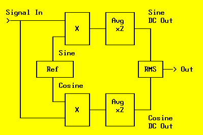
It differs only in the sign of the sum term, which we are going to filter out anyway. But the important thing is that it gives a full output value when the input is a cosine, as long as we use a cosine reference. So to create our improved analyzer we essentially need to double our first approach: We will need a reference frequency source with both sine and cosine outputs, feeding two different multipliers. The input signal will go to the other input of each multiplier, and the outputs will be independently averaged and doubled.
The true amplitude will be the vector sum or RMS value of the separate sine and cosine outputs (the square root of the sum of the squares).

Fig. 3: Conceptual Spectrum Analyzer
This circuit essentially performs a continuous Fourier transform as you move the reference through all possible frequencies. But since your time budget probably doesn't include infinity, and since you may not care about X-rays and gamma rays and such, you might want to limit the range of frequencies you look at.
Plus, even over a limited range, you may not care about resolving every frequency with infinite resolution... especially since you have to wait for the lowpass filter to settle to an average value at each one, and infinite frequency resolution means a big filter with infinite settling time.
So next time we'll look at how this simple circuit is used in real-world equipment, with modifications to make it faster and easier to use... including the Fast Fourier Transform (FFT).
If you don't have a spectrum analyzer available, you are welcome to download the author's Daqarta for Windows software for some free hands-on experience using your Windows sound card.
All Daqarta features are free to use for 30 days or 30 sessions, after which it becomes a freeware signal generator... with full analysis capabilities. (Only the sound card inputs are ignored.)
Fourier analysis is also covered in the Daqarta Help system under Spectrum (Fourier Transform) Theory. Or you can click right now on the above link to go directly to the Daqarta website version of the same Help system. It's all the same info, but you'll be missing out on the ability to follow along with the hands-on experiments... and the ability to do do useful work with your sound card afterward.
Previous Next
Features:
Oscilloscope
Spectrum Analyzer
8-Channel
Signal Generator
(Absolutely FREE!)
Spectrogram
Pitch Tracker
Pitch-to-MIDI
DaqMusiq Generator
(Free Music... Forever!)
Engine Simulator
LCR Meter
Remote Operation
DC Measurements
True RMS Voltmeter
Sound Level Meter
Frequency Counter
Period
Event
Spectral Event
Temperature
Pressure
MHz Frequencies
Data Logger
Waveform Averager
Histogram
Post-Stimulus Time
Histogram (PSTH)
THD Meter
IMD Meter
Precision Phase Meter
Pulse Meter
Macro System
Multi-Trace Arrays
Trigger Controls
Auto-Calibration
Spectral Peak Track
Spectrum Limit Testing
Direct-to-Disk Recording
Accessibility
Data Logger
Waveform Averager
Histogram
Post-Stimulus Time
Histogram (PSTH)
THD Meter
IMD Meter
Precision Phase Meter
Pulse Meter
Macro System
Multi-Trace Arrays
Trigger Controls
Auto-Calibration
Spectral Peak Track
Spectrum Limit Testing
Direct-to-Disk Recording
Accessibility
Applications:
Frequency response
Distortion measurement
Speech and music
Microphone calibration
Loudspeaker test
Auditory phenomena
Musical instrument tuning
Animal sound
Evoked potentials
Rotating machinery
Automotive
Product test
Contact us about
your application!
Questions? Comments? Contact us!
We respond to ALL inquiries, typically within 24 hrs.INTERSTELLAR RESEARCH:
Over 35 Years of Innovative Instrumentation
© Copyright 2007 - 2023 by Interstellar Research
All rights reserved