Software for Windows
Science with your Sound Card!


Features:
Oscilloscope
Spectrum Analyzer
8-Channel
Signal Generator
Spectrogram
Pitch Tracker
Pitch-to-MIDI
DaqMusiq Generator
(Free Music... Forever!)
Engine Simulator
LCR Meter
Remote Operation
DC Measurements
True RMS Voltmeter
Sound Level Meter
Frequency Counter
Period
Event
Spectral Event
Temperature
Pressure
MHz Frequencies
Data Logger
Waveform Averager
Histogram
Post-Stimulus Time
Histogram (PSTH)
THD Meter
IMD Meter
Precision Phase Meter
Pulse Meter
Macro System
Multi-Trace Arrays
Trigger Controls
Auto-Calibration
Spectral Peak Track
Spectrum Limit Testing
Direct-to-Disk Recording
Accessibility
Data Logger
Waveform Averager
Histogram
Post-Stimulus Time
Histogram (PSTH)
THD Meter
IMD Meter
Precision Phase Meter
Pulse Meter
Macro System
Multi-Trace Arrays
Trigger Controls
Auto-Calibration
Spectral Peak Track
Spectrum Limit Testing
Direct-to-Disk Recording
Accessibility
Applications:
Frequency response
Distortion measurement
Speech and music
Microphone calibration
Loudspeaker test
Auditory phenomena
Musical instrument tuning
Animal sound
Evoked potentials
Rotating machinery
Automotive
Product test
Contact us about
your application!
DFT Frequency Resolution
The frequency resolution is just the sample frequency divided by the number of samples (which is also the number of steps in the DFT sine table). If we have a sample rate of 10240 Hz for our 1024 samples, for instance, we will get 10 Hz resolution.
But what happens with an input of, say, 505 Hz falling between the 500 and 510 Hz reference frequencies? The multiplier product for each of these will contain a 5 Hz difference component, but it won't average to zero since our 1024 samples represent only 0.1 second... just one half-cycle of the full 5 Hz wave. The average value for a half-cycle of a sinusoid turns out to be 2 / pi or about 0.6366, so our spectrum analyzer will report both 500 and 510 Hz components, scaled to this fraction of the true magnitude that would have appeared at 505.
What's more, the 490 and 520 Hz reference products will contain 15 Hz difference components, and they won't average to zero either because we will have 1.5 cycles of these. The full cycle portion will average out, but the remaining half cycle is one third of the total so these components will show magnitudes scaled by 0.6366 / 3 or 0.2122.
The same phenomenon is repeated as we move farther above and below the true frequency: At 480 and 530 Hz we have 25 Hz components of which we have 2.5 cycles, with the half cycle making up 1/5 of the total so we have components scaled by 0.6366 / 5 = 0.1273. At 470 and 540 Hz we have components scaled by 0.6366 / 7, at 460 and 550 Hz they are scaled by 0.6366 / 9, and so on, giving "skirts" in our spectrum instead of one simple line. This effect is typically called leakage, since energy appears to have leaked from the true frequency to many other frequencies.
Another way to think about this whole situation is to consider that the spectrum is always correct, given that the input samples are treated as one unit of a repeating waveform. If the set of input samples contains an exact integer number of cycles, then additional identical sets of samples can be spliced together to make a seamless infinite wave. But if the set ends with a fraction of a cycle, the splices will cause abrupt steps every N samples:
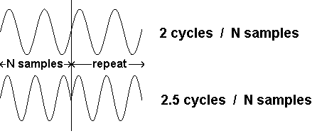
The spectrum of such a spliced infinite wave will have just the type of leakage skirts that we have seen:
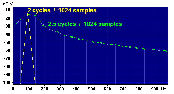
Note that the image shows leakage skirts mostly above the applied frequency, but if a higher frequency had been used they would appear below it as well.
These skirts, or "sidelobes" as they are often called, can be eliminated by changing the signal frequency to be an exact sub-multiple of the sample rate to prevent fractional cycles. If the signal is created by the Daqarta Generator, you can use the Lines frequency step option to insure this.
If this is not possible, a "window" can smooth the ends of the sample set to minimize the discontinuity. See Spectrum Window Theory for a full discussion.
See also Spectrum (Fourier Transform) Theory
- Back to Discrete Sine and Cosine References
- Ahead to Fast Fourier Transform (FFT)
- Daqarta Help Contents
- Daqarta Help Index
- Daqarta Downloads
- Daqarta Home Page
- Donate to Daqarta
Questions? Comments? Contact us!
We respond to ALL inquiries, typically within 24 hrs.INTERSTELLAR RESEARCH:
Over 45 Years of Innovative Instrumentation
© Copyright 2007 - 2026 by Interstellar Research
All rights reserved