Software for Windows
Science with your Sound Card!


Features:
Oscilloscope
Spectrum Analyzer
8-Channel
Signal Generator
Spectrogram
Pitch Tracker
Pitch-to-MIDI
DaqMusiq Generator
(Free Music... Forever!)
Engine Simulator
LCR Meter
Remote Operation
DC Measurements
True RMS Voltmeter
Sound Level Meter
Frequency Counter
Period
Event
Spectral Event
Temperature
Pressure
MHz Frequencies
Data Logger
Waveform Averager
Histogram
Post-Stimulus Time
Histogram (PSTH)
THD Meter
IMD Meter
Precision Phase Meter
Pulse Meter
Macro System
Multi-Trace Arrays
Trigger Controls
Auto-Calibration
Spectral Peak Track
Spectrum Limit Testing
Direct-to-Disk Recording
Accessibility
Data Logger
Waveform Averager
Histogram
Post-Stimulus Time
Histogram (PSTH)
THD Meter
IMD Meter
Precision Phase Meter
Pulse Meter
Macro System
Multi-Trace Arrays
Trigger Controls
Auto-Calibration
Spectral Peak Track
Spectrum Limit Testing
Direct-to-Disk Recording
Accessibility
Applications:
Frequency response
Distortion measurement
Speech and music
Microphone calibration
Loudspeaker test
Auditory phenomena
Musical instrument tuning
Animal sound
Evoked potentials
Rotating machinery
Automotive
Product test
Contact us about
your application!
Sound Card DC Pulse Output Circuits
- Introduction - The Problem
- Simple DC Pulse Converter
- Wide Range DC Pulse Converter
- LED Flasher / Modulator
- Low Frequency or Continuous DC Output
- Inexpensive All-In-One USB Device Modifications
Introduction - The Problem:
Suppose you want to use Daqarta to drive some external device that requires rectangular DC pulses (such as 0-5 V or 0-12 V), or to flash an LED.
The problem is that sound card outputs are AC coupled, which forces the output signal to maintain equal energy in the positive and negative directions, averaged over time, regardless of the digitally-generated waveform.
For example, if you create a Generator setup that shows only positive values on its output display channel, such as a square wave with Level at 50% and Offset at +50% to get a range from 0 to +100% of full-scale, the actual output will quickly settle into a square wave at +/-50% of full-scale.
In addition, at low frequencies the AC coupling (which is essentially just a simple high-pass filter) causes a droop in the response. The tops and bottoms of a true square wave are DC levels which the filter doesn't pass; it passes the transitions, but then decays toward zero as time proceeds. (This droop isn't obvious at high frequencies, since the decay doesn't get very far before the next transition.)
Both of these phenomena are shown below. The green trace shows a 25 Hz square wave between 0 and 100%; the yellow trace shows the output waveform that would be produced by a typical AC-coupled sound card. It swings equally about 0, with a droop of nearly 50% in each 20 msec phase. The transitions still cover the same vertical distance, but they don't start and end at the same points as the original.
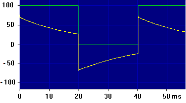
(Note that this image was not created using the Daqarta Generator with the output looped back to the input to observe the waveform. That would have imposed two AC-coupling time constants, one from the output and one from the input. Instead, a DC-coupled external square wave was used as the input source; the green trace is what would have been seen with a DC-coupled sound card.)
Furthermore, sound cards typically produce output signals of less than +/-2.5 volts maximum. These limitations pose problems when driving external equipment that expects unipolar signals at higher levels. For example, most lab equipment specifies 0-5 volts (known as TTL levels) for things like trigger and sync inputs. Hall-type crank/cam sensor inputs on certain engine electronic control modules may require pulses of 0-5 volts or 0-12 volts.
These and similar applications require either an internal modification or an external circuit to convert the low-voltage AC waveform to a ground-referenced DC waveform at a higher voltage. Two different external circuit designs are presented; a simple discrete-part design, and a wide range design that handles especially wide pulses and low-frequency square waves, regardless of AC coupling droop.
In addition, the Inexpensive All-In-One USB Device Modifications topic discusses two different approaches to modifying existing USB sound cards to provide 0-5 V rectangular signals without any external circuitry or power supply. (You could build either of the other circuits into an existing USB sound card case, but the circuits presented here are simpler and offer better performance.)
Note that before you build any of these, you should consider if you can use the much simpler approach covered in the Simple Sound Card Unipolar DC Modification topic. This involves only soldering 100 ohm resistors across the output capacitor terminals of an inexpensive USB sound device... under US $10 for a 2-channel device, and no circuit construction required. (About US $25 for 6 channels.)
The possible drawback of this simple approach is that the output signal does not swing all the way down to ground, nor as high as +5 V. With the specified 2-channel device the range is about 0.6 to 2.7 V, and with the 6-channel it is about 0.1 to 4.3 V.
Still, that limited range is probably "good enough" for many applications, including driving devices that are expecting a nominal 0-5 V, such as crank/cam Hall sensor inputs to engine ECU/ECM modules; they usually have generous safety margins. The traditional 'TTL' input spec is 0.8 V or less for 'low' and 2.0 V or more for 'high'. Modern CMOS inputs are even more tolerant. So you might want to try the simple modification first, to see if it meets your needs; you can always upgrade it to a true 0-5 V circuit later.
Alternatively, you may be able to use an inexpensive Arduino or Numato device that has 0-5 V digital outputs capable of driving LEDs. (You'll need a current-limiting series resistor for each.) For the Arduino, the Arduino_Oscillators macro mini-app allows up to 4 square waves with adjustable frequency and phase. The DaquinOscope additionally offers the same oscillators, with an option to use one of them as an arbitrary waveform generator that can provide 8 digital outputs with any desired pattern and rate. For the Numato or the Arduino you can write simple macro code to control 8 or more digital outputs as needed, such as in response to digital inputs.
If you do need to build one of the DC pulse circuits below, note that they are only for rectangular Generator waveforms such as Square or Pulse, not Sine, Triangle, or Ramp.
Pulse waves should typically be monophasic (unipolar) by setting Pulse B Width and Level to 0, Pulse A Level to +100%, and 0 Level (baseline) to -100% to get a +/-100% swing like a square wave.
One potential issue to be aware of is overdriving the sound card output amplifier, such that the waveform is clipped. Since the waveform is a pulse or square wave that has a flat top already, clipping may seem irrelevant. But an overdriven amplifier may behave badly, introducing spurious "glitch" events in the clipped waveform. This is especially likely when the sound card is creating rectangular waveforms, which exhibit Gibbs phenomenon due to steep-cutoff output filters. That introduces apparent "overshoot" and "ringing" at transients such as rectangular wave rise and fall edges, which can drive the amplifier in and out of clipping and hence provoke multiple glitch events on every edge. The cure or prevention is to simply reduce the output level.
Both circuits presented here require external power, which may be provided by the circuit being driven (such as the sensor supply or the 12 V car battery for a crank/cam sensor simulator), or by 5 V power "stolen" from a spare USB port, or from a separate battery such as a 9 V "transistor" type.
Note that for crank/cam sensor simulations, only Hall-type (3-terminal) sensors typically need this DC pulse conversion. Inductive (2-terminal) types generate AC waveforms, which Daqarta can create with a normal sound card. Instead of a DC pulse converter you may need an isolation transformer, if the sensor is not normally grounded to the automotive ground.
Simple DC Pulse Converter:
Here is a simple DC pulse converter that uses readily available discrete parts that you may already have on hand, can be easily thrown together on a scrap of perfboard, and can use anything from +5 to +15 volts for power. Its main limitation is that it can't handle very wide pulses, very high duty-cycle pulses, or very low-frequency square waves. (See the Wide Range DC Pulse Converter, below, if you need those.)
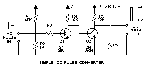
Q1 is biased by R1 and R2 such that when the sound card output pulse goes high, it will exceed the 0.6 V threshold needed to switch the transistor on. When that happens, the Q1 collector is pulled low. Then Q2 and R5 provide a logic inversion such that a high input gives a high output.
Unlike the Wide Range DC Pulse Converter, this circuit is limited by the sound card AC coupling droop. At low square wave frequencies (wide high pulses), the droop may fall below the circuit threshold and turn it off prematurely... and usually not very neatly, with spurious chatter as it does so. A reasonable upper limit to wide pulse widths is about 5-10 msec, which means square waves must be 50-100 Hz or above. (There is no lower frequency limit on positive pulses, however, as long as they are not wider than 5-10 msec.) These are "worst-case" limits based on the worst sound card tested (highest low-frequency -3 dB response, at 14 Hz); most cards are an order of magnitude better.
Also, pulse duty cycle can't be higher than about 75% maximum, because AC coupling causes the average value of the overall output waveform to be zero. As duty cycle increases and the output is mostly high, the average value gets closer to the maximum value. After the AC coupling the output is near zero, with negative pulses... nothing to turn on Q1.
The Q2/R5 inverter may be omitted for some applications, including most Hall-type crank/cam sensor simulators. In that case, you should go to External Gain in the Calibration menu and set the sign of the appropriate Wave Out control to negative. (The numerical value is not important here.) The display of the generated waveform will be unchanged, but the actual sound card output will be inverted. Then the Q1 circuit will invert it back to what the screen shows.
Note, however, that this trick will only work if the desired pulse train is more-or-less square, not low duty-cycle positive pulses. That would cause the (inverted) sound card D/A waveform to be mostly high with pulses down to zero, which after AC coupling (as noted above) would be near zero with negative pulses that can't turn on Q1.
In general, you should include the Q2 stage for one-pulse-per-revolution engine sensor simulations, since the duty cycle is very low. But for typical multi-tooth sensors, even with gaps, you can get away without it. (It's probably a good idea to include it, however, since it not only eliminates the need to change the External Gain sign, but avoids confusion if you monitor the output with a separate scope. And you'll be prepared for future applications as well.)
When using this circuit, be sure to consider the Gibbs phenomenon issues discussed in the Introduction. Don't run with the sound card output at maximum unless you first thoroughly test the card and circuit together.
If you need 5 volt output pulses, but you want to use a higher supply voltage for this circuit, you can add R6 to divide the voltage down to 5 volts (or whatever you need). With R5 = 10K, supply voltage Vs, and desired output voltage Vo, you can use the voltage divider formulas to find R6:
R6 = Vo * R5 / (Vs - Vo)
For example, to get 5 V from a car battery (which is really closer to 13 V than the nominal 12 V), you'd use:
R6 = 5 * 10K / (13 - 5) = 6.25K
Don't obsess over getting the exact value; the nearest standard value in the 5% series will be more than adequate in almost all cases. In this case, 6.2K is a standard value, but to get 5 V from a 9 V battery you'd use:
R6 = 5 * 10K / (9 - 5) = 12.5K
You can thus choose either 12K or 13K for R6.
The Simple DC Pulse Converter schematic plus complete 600 DPI board and parts placement layouts suitable for printing are included in the PulseOutQAll600.PNG file that is installed with Daqarta in the Documents - Daqarta - Circuits folder.
Be sure to read the Notes section of Daqarta Printed Circuits before you begin.
You can use the printed layouts directly to create your own circuit boards, with either the laser printer toner transfer method, or with the direct-draw method discussed under Printed Circuit Construction.
However, the circuit is simple enough that you may want to just assemble it directly on perfboard, instead of creating a printed circuit. You can use the PulseOutQAll600.PNG component layout drawing to guide your parts placement.
Alternatively, you can edit the PulseOutQ.PCB file in the same folder to make custom modifications first. See the PCB Files discussion in Daqarta Printed Circuits for the required software to use this file, and for information on how to submit it to have boards made by a 3rd-party supplier.
Wide Range DC Pulse Converter:
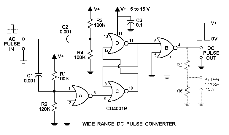
Unlike the prior Simple DC Pulse Converter, which works on a simple level threshold, this circuit uses edge detection. Separate rising and falling edge detectors drive a set-reset flip-flop, setting it on a rising edge and resetting on a falling edge. This allows operation at ultra-low frequencies and duty cycles without regard to AC coupling droop or pulse polarity. It will also operate at well over 100 kHz, or with single pulses as narrow as one sample from the sound card. It will run on power supply voltages from 5 to 15 volts with no modifications.
The heart of the circuit is a CD4001B CMOS quad dual-input NOR gate. (The 'B' indicates that the outputs are buffered, which is important for proper circuit operation. Don't use the older 'A' series.) Gates C and D form the set-reset flip-flop, which is set or reset by high pulses at pins 13 or 9, respectively.
CMOS gates have logic thresholds that are always half the power supply voltage. The pin 13 input to gate D is biased just below threshold (45.5% of the supply voltage) by R3 and R4 acting as a voltage divider. A rising input edge produces a brief positive pulse through C2, driving pin 13 above threshold to set the flip-flop: high on the gate C output, low on the D output. The low D output is inverted by gate B to become high at the overall circuit output at pin 4. (The C output could have been used directly, but the B gate was available.)
Gate A detects falling edges. Note that the R1 and R2 values are the opposites of R3 and R4, so they bias pin 1 just above threshold. A falling edge produces a brief negative-going pulse from C1, which pulls pin 1 below threshold. Since gate A is wired as an inverter (its other input is grounded, and a NOR output is high only if both inputs are low), this causes a brief high pulse from its output. That feeds pin 9 of gate C to reverse the flip-flop state, making the overall circuit output low.
You may notice that the time constant of each edge detector is over 50 microseconds (0.001 microfarad times 54.5K, the parallel equivalent of 100K and 120K), and in fact the pulses these produce are in the range of 100 microseconds. At first glance that would seem to limit square wave operation to frequencies of 5000 Hz or less (100 usec each phase), before the 'on' edge pulse collides with the 'off' pulse in a battle for control of the flip-flop. But it turns out that this isn't a problem, because each edge pulse is cut short by the arrival of the opposing edge at its gate input. That's what allows this circuit to operate in the 100s of kHz range.
The use of edge detection instead of level detection (as used in the Simple DC Pulse Converter) is vital for low frequency or wide pulse operation. Recall that even on a slow square wave with lots of droop from the sound card AC coupling, the edges have the same net vertical (voltage) change:
Only the net size of that voltage change determines the size of the brief pulse that triggers a flip-flop state change. The absolute value of the starting voltage is blocked by C1 or C2, which only lets the transient pass. A simple level detector would turn off too early, when the sound card output drooped below the threshold.
R5 and R6 form an optional voltage divider to reduce the output level below the supply level. You might want to use this to get 5 V pulses when running from a 9 V battery or a 12 V car battery, for example. Another use is to provide a low-level version of the output that can be monitored by the sound card input; 1 V is a good value for this.
C3 is a ceramic 0.1 microfarad decoupling capacitor; it is not an absolutely essential part of the circuit, but it is included to help prevent crosstalk between gate outputs and the edge-detecting inputs which are biased close to threshold. (Be sure to use a ceramic capacitor, not a film type.)
The V+ supply voltage you use affects the minimum Vin pulse or square wave level that the sound card must supply. Typical peak-to-peak values are:
    V+      Vin
    5 V     0.5 V
    9       1.2
    13      2.0
    15      2.5
When using this circuit, be sure to consider the Gibbs phenomenon issues discussed in the Introduction. Don't run with the sound card output at maximum unless you first thoroughly test the card and circuit together.
The Wide Range DC Pulse Converter schematic plus complete 600 DPI board and parts placement layouts suitable for printing are included in the PulseOutWAll600.PNG file that is installed with Daqarta in the Documents - Daqarta - Circuits folder.
Be sure to read the Notes section of Daqarta Printed Circuits before you begin.
You can use the printed layouts directly to create your own circuit boards, with either the laser printer toner transfer method, or with the direct-draw method discussed under Printed Circuit Construction.
Alternatively, you can edit the PulseOutW.PCB file in the same folder to make custom modifications first. See the PCB Files discussion in Daqarta Printed Circuits for the required software to use this file, and for information on how to submit it to have boards made by a 3rd-party supplier.
LED Flasher / Modulator:
Either of the above circuits can be modified to flash or modulate an LED. The Simple DC Pulse Converter can be made even simpler when used for this purpose. Omit Q2, R5, and R6, and replace R4 with the LED (arrow pointing down) plus series resistor Rlim to limit the current:

The proper value for Rlim is determined by the maximum current I through the LED, its "on" voltage Vled, and the supply voltage V (labeled 'V+' on the diagram).
Rlim = (V - Vled) / I
You can use Vled = 2 V as a good approximation for most common red, yellow, and green LEDs.
The collector of Q1 provides a logically-inverted monitor signal: When the input goes high, Q1 goes on and pulls the collector low, turning the LED on. So even though the monitor output is inverted, the LED state is the same as the input... you should not invert the External Gain value in this case.
If you want a non-inverting monitor, just build the orignal Simple DC Pulse Converter with Q2 and R5 (and optionally R6), but replace R4 with Rlim and the LED. If you use the PulseOutQAll600.PNG printed circuit board, you can mount Rlim and the LED off-board.
If you opt for the simpler inverted monitor, you can use the board without Q2 and R5/R6, using the former R4 connection at the Q1 collector for the inverted monitor. Install the LED in the former Q2 base and collector holes, and install Rlim instead of the former R5.
Please note that this circuit has the same limitations when driving the LED as the original had for electrical signals: You can't hold the LED fully on for more than 5-10 msec, and you can't use a pulse train that is high more than about 75% of the time, maximum. That means that if you use pulse width modulation (PWM) to control the brightness of the LED, it can never be brighter than 75% power.
The 5-10 msec 'on' limit would seem to preclude flashing the LED at a slow rate, such as 1 second on and 1 second off. But if you will accept flashes that are less than 100% brightness, you can still do it.
Set Tone Freq to (say) 1000 Hz, then go to Wave - Pulse. Set the Width Units to Percent. Set Pulse B Width = 0, Pulse A Level = 100%, Pulse B Level = 0, and Pulse 0 Level = -100%.
Now set Pulse A Width to the highest value (brightest LED glow) you can, then back off 5-10% as a safety margin for reliable operation. That will be the 'on' brightness.
To flash the LED, go back to the main Stream dialog and open the Modulation - Burst dialog. Set Lag=0, and set the little button to the right of it to 'sec' if it is currently at 'Smpls'. Set Rise=0 and Fall=0. Now set High to the desired 'on' duration, and Cycle to the desired total cycle duration (sum of on and off times). Toggle Burst On active at the top of the dialog, and the LED should start flashing.
Alternatively, you can get arbitrarily-long flashes and full-range brightness modulation using the Wide Range DC Pulse Converter:
Replace R5 with Rlim, and replace R6 with the LED. Note, however, that this circuit can't directly drive the LED with as much current as Q1 in the Simple circuit. Q1 can handle 100 mA, while the CD4001B can only handle about 10 mA. If you need more current than that, other than for brief flashes, omit R6, replace R5 with 10K, and connect its free end to the base of a 2N3904 with its emitter connected to ground and its collector to an LED and Rlim as in the previous Simple circuit.
With this circuit you can easily flash the LED with equal on and off times, no matter how slow, without Pulse adjustments or Burst modulation; just set Wave to Square and set Tone Freq for the flash rate.
Note that with either of the above circuits, the LED can be part of an optoisolator. This allows design of isolated circuits for safe control of high-power and/or high-voltage devices, or for isolated electrical stimulation of living subjects.
Low Frequency or Continuous DC Output:
If you need continuous DC output, and it doesn't need to go all the way down to zero, you should investigate the much simpler approach covered in the Simple Sound Card Unipolar DC Modification topic. That involves only soldering 100 ohm resistors across the output capacitor terminals of an inexpensive USB sound device... under US $10 for a 2-channel device, and no circuit construction required. (About US $25 for 6 channels.)
That simple approach does not allow voltages all the way down to ground, nor as high as +5 V. With the specified 2-channel device the range is about 0.6 to 2.7 V, and with the 6-channel it is about 0.1 to 4.3 V.
For certain applications, you may be able to use an inexpensive Arduino board together with the DaquinOscope macro mini-app running a wavetable oscillator using a simple R-2R ladder DAC to get 8-bit resolution from 0 to 5V at frequencies from 0 to 20 kHz.
An alternative for low output voltages at low frequencies is to use unipolar Pulse waves with either of the DC Pulse Converter circuits. This allows adjustable duty cycle, and PWM allows modulation of that duty cycle. A simple RC low-pass filter can turn the duty cycle into a constant or low-frequency DC value.
Note that unlike the above-mentioned simple USB sound card approach, this method will have some output ripple, along with coarser level resolution. Some adjustments and compromises should be expected.
Set Tone Freq in the 100 to 1000 Hz range, and use a 10K and 10 uF filter as a starting point. That has a cutoff frequency of:
    F = 1 / (2 * pi * R * C).
    F = 1 / (2 * pi * 10000 * 10*10^-6)
    F = 1.6 Hz
For the Simple DC Pulse Converter, you connect this filter to the Q2 output. For the Wide Range DC Pulse Converter, you can use the existing PulseOutWAll600.PNG circuit board from the Documents - Daqarta - Circuits folder, and just make R5 = 10K and use a 10 uF capacitor instead of R6. In either case, be sure to observe the polarity markings on the capacitor, with the negative side going to ground.
The output of the filter will be the duty cycle (Pulse A Width, with Width Units to Percent) times the V+ supply voltage. (Make sure that Pulse B Width = 0, Pulse A Level = 100%, Pulse B Level = 0, and Pulse 0 Level = -100%.) This voltage assumes that you monitor it with a high impedance device; if not, you may want to follow the filter with an op-amp buffer, using half of an LT1013 dual rail-to-rail single-supply op-amp run from the same supply as the Pulse Converter.
You'll probably need the output level set close to maximum, but still avoiding clipping. As noted earlier, the Simple circuit can't use a high duty cycle... 75% is probably the limit, but test your own setup. The Wide Range circuit should be able to handle one low sample and the rest high. The exact duty cycle then depends on the sample rate and Tone Freq.
With Tone Freq = 1000 Hz, and the default 48000 Hz sample rate, there are only 48 samples per cycle. That means that you only have 48 possible duty cycles... possibly too coarse for adjusting the value for some external use. Using PWM, the output may have noticeable steps.
On the other hand, at 100 Hz you have 480 samples per cycle, giving good resolution and tiny modulation steps. However, the filter has a harder time removing the pulses to get DC values... you'll see noticeable ripple of around 100 mV.
You can reduce the ripple by using larger R or C. Note that if you increase R, the filter is more sensitive to loading by whatever you connect to it, unless you use a buffer amp.
If you are using PWM, the filter will limit how fast you can modulate the output. The original 1.6 Hz filter response is fine when modulating at 0.1 Hz or less, but the output swing will be about half as big at 1 Hz, and falls roughly by half for each doubling of frequency above that (-6 dB/octave).
Note that when using PWM you should usually set Pulse A Width to 50%, so that the modulation can swing equally above and below that. You can't set Mod Depth much above 90% with Tone Freq = 1000 Hz, but at 100 Hz you can usually get to 99% Depth.
Note that the Simple circuit can't get to the high duty cycles needed for the above PWM Depth ranges, but you can still take steps to get the largest range possible. Start with PWM off and find the maximum Pulse A Width. You can monitor the pulse output of the DC Pulse Converter at the Q2 collector, just before the filter. Monitor on Line In, adjusting the Line Level to avoid clipping. (You may need to add a separate voltage divider if you are using V+ greater than 5 V.)
Adjust Pulse A Width to the largest percentage that gives a mostly-high output but still produces a detectable low pulse on each cycle. (Due to AC coupling on Line In, there may be a lot of droop in the display.)
Note that Pulse A Width percentage, which will be the maximum modulation depth that doesn't try to modulate below 0. Then set Pulse A Width to half that value before going to the PWM dialog.
For example, if you found that Pulse A Width = 70% produced reliable low pulses, you'd set Pulse A Width = 35% and set PWM Mod Depth to 70%. The PWM would then extend from 0% (totally off) to 70% duty cycle.
Once again, you don't need to do any of this with the Wide Range circuit, just set Pulse A Width to 50% and PWM Mod Depth to 90-99% depending on Tone Freq.
Inexpensive All-In-One USB Device Modifications:
Here we discuss two approaches to getting 0-5 V DC pulse outputs by modifying existing USB sound card devices. These circuits are integrated into the original case and use the USB port to supply power. By using the original output jacks as well, you can make a neat all-in-one package.
We'll use two different USB devices, a tiny one that is built into an oversize USB plug and provides two output channels, and a larger one that supports 6 outputs.
2-Channel Plug-Type USB Modification:
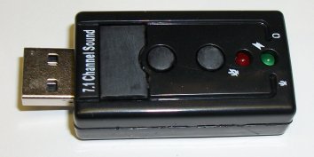
This circuit uses a very inexpensive "virtual" multi-channel USB sound device... under US $10 with free shipping from China. Search for 'virtual 7.1 channel USB sound adapter' and look for this image:
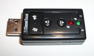
Despite the '7.1 channel' claim, it actually has only stereo outputs, with a single-channel microphone input which we will ignore here. See the following Multi-Channel USB Modification for true 6 to 8 channel sound cards.
This unit was chosen for ease of modification, with a roomy interior to house our added circuit once some unwanted switches are removed.
Note that there are multiple devices using the same case, two of which were discussed in the Simple Sound Card Unipolar DC Modification topic for the 2 Channel USB Plug-Type Sound Card. That modification is much simpler than the approach discussed here, although its outputs only provide a limited range of +0.6 to +3.9 V (first device) or +0.6 to +2.7 V (second device), not a true 0-5 V like this one. Nevertheless, you may want to test that simple approach first; you can upgrade the same unit to true 0-5 V later, if needed.
The circuit uses a CMOS CD4001B quad NOR gate in a standard 14-pin plastic DIP package. Two gates are used for each channel:
Depending on which variant of the USB device you get, the inside may look like this:
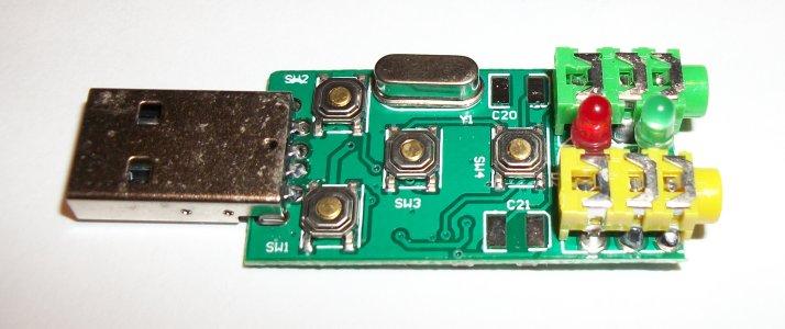
Or like this:

Lacking a crystal can, the second unit is roomier. It is probably the one you will get if you pay US $10 or less. Nevertheless, the following instructions are for the first unit, which is now more expensive. The internal component numbers (switches and capacitors, etc) are different, but otherwise the principles are the same.
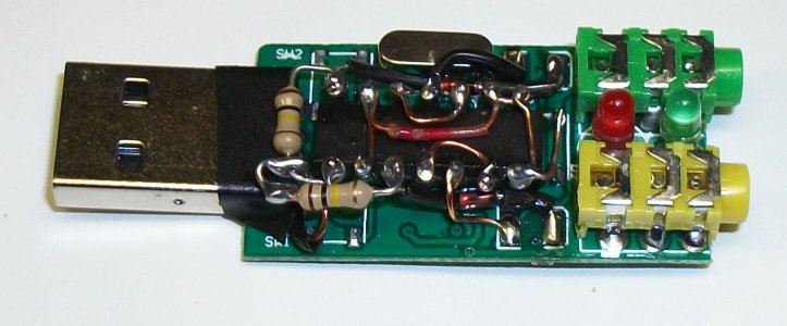
The four switches SW1 - SW4 are easily removed by inserting a thin (jeweler's) screwdriver blade under each switch and prying gently. Then use side-cutters and needle-nose pliers as needed to remove any remains. The resulting board will look like this:

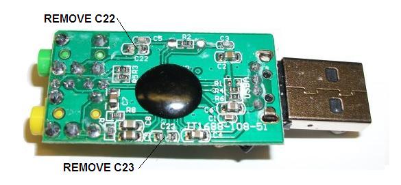
Note the large solder pad pairs marked C20 and C21. These are where we will connect the CMOS circuit inputs and outputs. (And where the 100 ohm resistors would have been used in the simple modification mentioned earlier.) C20 is the Right channel, and C21 is the Left. These empty pads were apparently provided to allow for insertion of larger output capacitors in parallel with the existing capacitors C23 and C22, respectively, on the bottom side of the board.
Those existing capacitors need to be removed first. This is easily done by snipping their centers out with sharp side-cutters:
The CMOS chip is installed in inverted "dead bug" fashion, with its legs in the air. You should do as much of the circuit wiring as you can before installing the chip. Here is the wiring diagram, as you would see the inverted chip while working on it:
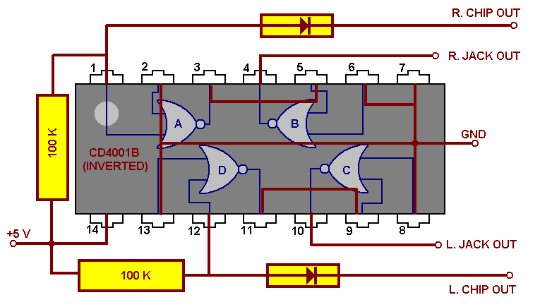
For use during construction, this image with the circuit diagram and final assembly photo (see below) can be printed from the DC_2PulseOutAll600.JPG file that is installed with Daqarta in the Documents - Daqarta - Circuits folder. Since there is no circuit board layout that needs to be printed to scale, you can print it directly from Windows Explorer via Media Viewer and use "fit to page".
You may find it helpful to stick the chip to the benchtop with double-sided tape, to hold it steady while you work on it.
Before you install this assembly, you should prepare the power and ground connections on the USB board. On the top of the USB board, connect a short (1 inch) piece of bare wire to the +5 V pin of the USB connector, as labeled in red at the lower left of the board-top photo. CAUTION: the solder pad for this pin is very close to the ground pad of SW1. Tin the end of the wire with solder first, leaving a small blob at the tip. Then carefully hold it on the solder pad while you apply a fine-tipped soldering iron to the joint. The wire should come out straight down, parallel to the board surface, as shown in the photo.
If you wish, you can avoid that tight soldering job by connecting to the same USB pin on the bottom of the board, using a longer insulated wire and notching the plastic case so it can wrap around to the top side. (The notch can be created by a touch from a hold soldering iron.)
The ground can likewise be connected at the USB connector, at the opposite end from the +5 pad. Note that the adjacent ground pad from SW2 is directly connected, as is the pad directly above it at the upper left in the photo, so there is no problem soldering to the top.
However, the wiring diagram shows the ground connection at the opposite end, where the pin 7 ground of the CD4001B is connected to the pin 8 input to the C gate. That connection was made to the SW4 ground pins, which are those directly adjacent to the plastic audio jacks. There are several other ground points on the USB board; you can verify these using a DMM on 'Ohms' range, and use whichever is convenient.
Before installing the chip assembly onto the USB board, clip off any excess lead length from the CD4001B pins. Position the chip assembly near the USB connector and solder the wire from +5 V to the junction of the 2 resistors. Then connect the ground to the chosen location. Next, solder the two diode ends to the C20 and C21 pads nearest the plastic jacks. Finally, solder the two chip outputs to the remaining C20 and C21 pads.
The final assembly is shown here:
Note that black insulating tubing (not shrink tubing) was slipped over the diode leads before they were installed, as well as over the chip output to C20 and the +5 V wire. (This could have been used instead of the brown insulated wire with red markings at the middle of the chip.) If you don't have insulating tubing, you can strip the insulation from a larger wire size than you are using for hookup. Apply as needed to prevent shorts.
Also note the piece of electrical tape covering the shell of the USB connector, preventing contact by the leads of the two resistors (and the wire from +5 V) from shorting to the grounded USB shell. You can slip the tape in after everything else is assembled.
The plastic buttons that originally activated the 4 switches are no longer needed, but you may want to re-install them just to occupy the holes in the plastic case. You'll need to snip off the switch-activating columns from each button, and you may want to sand off the original labels to make it obvious that the buttons are no longer functional. Then glue the buttons into the top of the case, since they will no longer be supported by the switches.
Multi-Channel USB Modification:
The device used here is readily available on the Web, with prices typically about US $25. Its performance as a normal sound card is documented in Sound Card Performance Tests, where it is referred to as '5.1 Channel CM6206 USB'. It is also used for the Simple Sound Card Unipolar DC Modification and the Sound Card DC Input / Output Modification topics discussed under DC Measurements And Outputs.
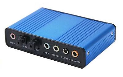
Unfortunately, it doesn't have a specific name or model number to search for. Try "USB 5.1 Sound" and look for a matching photo. The unit shown here was purchased from HDE through Amazon.
This device provides 6 independent output channels, any or all of which can be modified to provide 0-5 V pulse outputs.
The pulse output modification uses a CMOS CD4001B quad NOR gate in a standard 14-pin plastic DIP package. It provides 4 outputs; if you need to drive all 6 outputs on the USB device, build a second circuit and ignore 2 of the outputs. (You can also use two of these circuits to provide 8 outputs from the '7.1 Channel CM6206 USB' device or similar.)
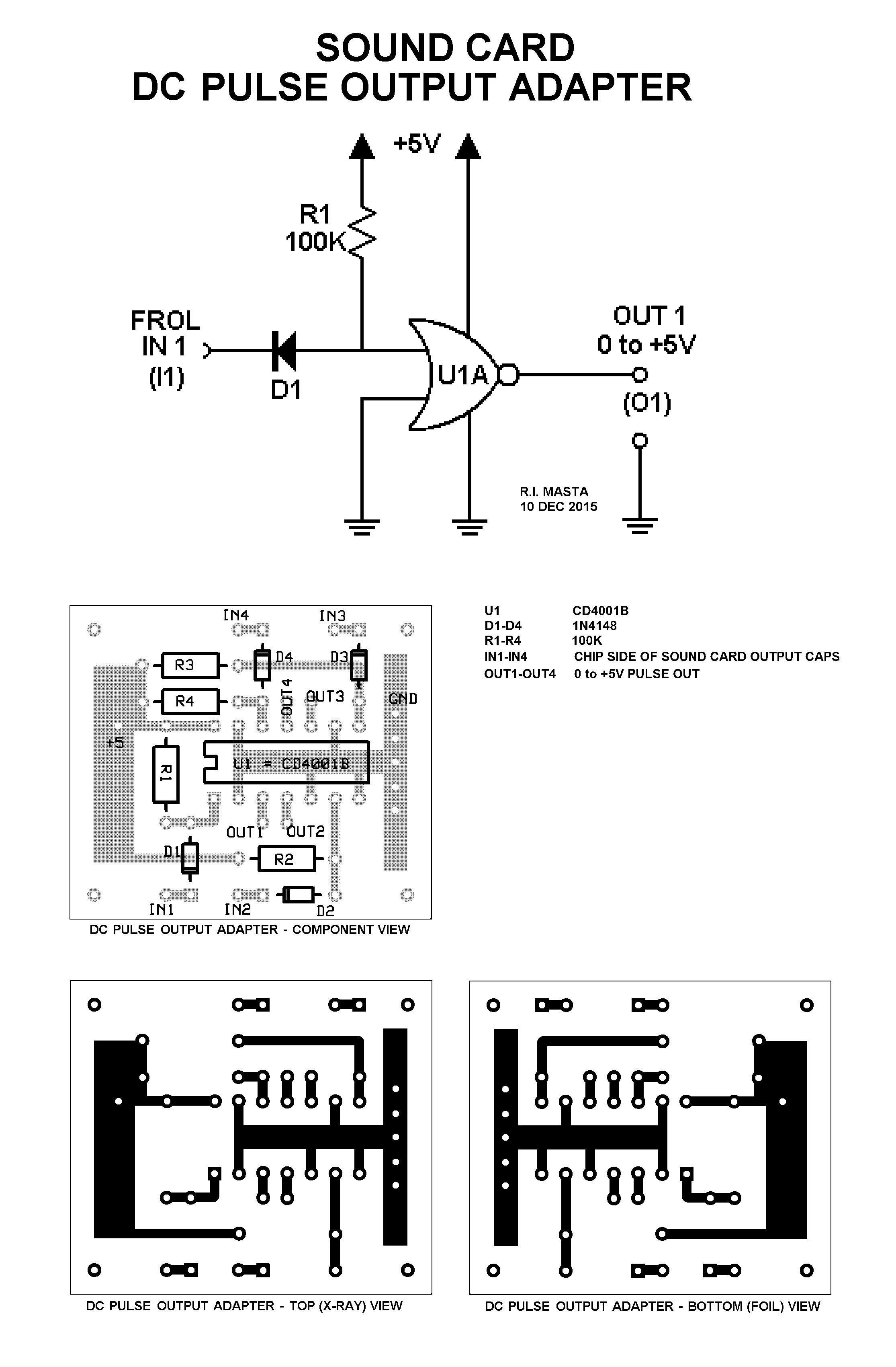
This schematic shows only one of the 4 outputs from the CD4001B, assumed here to be Front Output Left (FROL, using the CM6206 pin nomenclature). The others are identical and interchangeable.
Note that the output is logically inverted; this is no problem since Daqarta can compensate for that if you enter a negative value into Daqarta's Full-Scale Range or External Gain controls. However, you must perform an Auto-Calibration before these controls can be used.
The above schematic plus complete 600 DPI board and parts placement layouts suitable for printing are included in the DC_PulseOutAll600.PNG file that is installed with Daqarta in the Documents - Daqarta - Circuits folder. The board is very small, and two of them can easily be tucked into the original USB case.
Be sure to read the Notes section of Daqarta Printed Circuits before you begin.
You can use the printed layouts directly to create your own circuit boards, with either the laser printer toner transfer method, or with the direct-draw method discussed under Printed Circuit Construction.
Alternatively, you can edit the DC_PulseOut.PCB file in the same folder to make custom modifications first. See the PCB Files discussion in Daqarta Printed Circuits for the required software to use this file, and for information on how to submit it to have boards made by a 3rd-party supplier.
Construction Details:
Remove the two screws that hold the rear panel onto the USB device, and push gently on the big black SPDIF TOSLINK dummy plugs to slide the circuit board and connectors out the back of the case. The board should look like this:
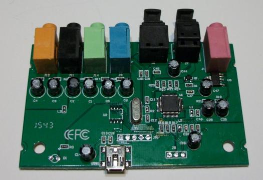
As discussed under Output and Reference Connections in the Sound Card DC Input / Output Modification topic, the output capacitors are the row of 6 black electrolytics near the upper left in the image. The capacitor numbering, starting from the right end of the row and moving left, is shown below, along with the CM6206 chip labels for reference:
    C6  Front Left  (FROL)
    C5  Front Right     (FROR)
    C1  Rear Left       (SSOL)
    C2  Rear Right      (SSOR)
    C3  Center (Left)   (CENO)
    C4  Bass (Right)    (LFEO)
These make more sense when viewed from the bottom:
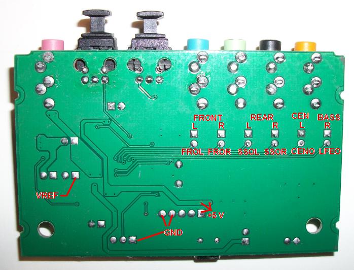
You will need to remove each of the capacitors. Since it can be difficult to desolder them without damaging the USB board, you may prefer to cut them out from the top. Use caution to avoid scraping the solder mask coating from beneath the capacitors.
After capacitor removal you'll need to connect the CM6206 outputs (the lower row of round capacitor pads shown in the photo) to the 'IN' connections of your circuit, and connect the top row of square pads to the 'OUT' connections for the audio jacks.
Connect +5 V and ground to your circuit from the USB board locations shown in the photo. (Ignore the VREF label.)
Since you will need to install the circuit board on the top side of the USB board, it seems reasonable to make the connections there. However, it is much easier to solder to the bottom pads, then route the wires up to your circuit board through the large holes at lower left and right in the photo.
Note: You should also consider replacing the USB socket with a direct cable connection. See "USB Socket Replacement" under "Construction Details" in the Sound Card DC Input / Output Modification topic.
- Back to Sound Card External DC-to-AC Modulator
- Ahead to Sound Card Duplex, Half and Full
- Daqarta Help Contents
- Daqarta Help Index
- Daqarta Downloads
- Daqarta Home Page
- Donate to Daqarta
Questions? Comments? Contact us!
We respond to ALL inquiries, typically within 24 hrs.INTERSTELLAR RESEARCH:
Over 45 Years of Innovative Instrumentation
© Copyright 2007 - 2026 by Interstellar Research
All rights reserved