Software for Windows
Science with your Sound Card!


Features:
Oscilloscope
Spectrum Analyzer
8-Channel
Signal Generator
Spectrogram
Pitch Tracker
Pitch-to-MIDI
DaqMusiq Generator
(Free Music... Forever!)
Engine Simulator
LCR Meter
Remote Operation
DC Measurements
True RMS Voltmeter
Sound Level Meter
Frequency Counter
Period
Event
Spectral Event
Temperature
Pressure
MHz Frequencies
Data Logger
Waveform Averager
Histogram
Post-Stimulus Time
Histogram (PSTH)
THD Meter
IMD Meter
Precision Phase Meter
Pulse Meter
Macro System
Multi-Trace Arrays
Trigger Controls
Auto-Calibration
Spectral Peak Track
Spectrum Limit Testing
Direct-to-Disk Recording
Accessibility
Data Logger
Waveform Averager
Histogram
Post-Stimulus Time
Histogram (PSTH)
THD Meter
IMD Meter
Precision Phase Meter
Pulse Meter
Macro System
Multi-Trace Arrays
Trigger Controls
Auto-Calibration
Spectral Peak Track
Spectrum Limit Testing
Direct-to-Disk Recording
Accessibility
Applications:
Frequency response
Distortion measurement
Speech and music
Microphone calibration
Loudspeaker test
Auditory phenomena
Musical instrument tuning
Animal sound
Evoked potentials
Rotating machinery
Automotive
Product test
Contact us about
your application!
DaquinOscope Mini-App
- Introduction
- Operation
- Main Controls
- Trigger Timing Controls
- Oscillators and Misc. Controls
- Variable, Control, and Array Usage
- DaquinOscope Macro Listing
- _Dscope_Acq_Mode Macro Subroutine Listing
- _Dscope_Ctrls Macro Subroutine Listing
- _Dscope_Task Macro Subroutine Listing
- _Dscope_Write Macro Subroutine Listing
Introduction:
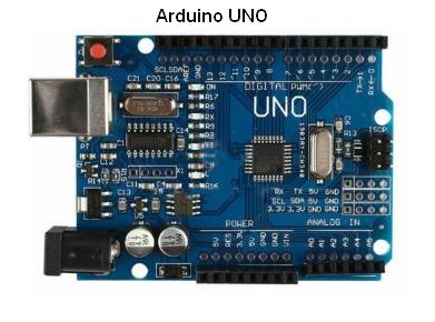
The DaquinOscope macro mini-app is included with Daqarta. It uses an Arduino Uno running DaqPort to collect and display 1, 2, or 4 simultaneous 0-5 VDC analog channels or 1, 2, 4, or 8 simultaneous 0-5 V digital channels.
AC input signals can be used via a simple AC-to-DC Input Level Shifter and Limiter circuit for each line. This converts signals up to +/-2.5 volts AC to 0-5 V DC, such that the original analog zero becomes +2.5 V, while -2.5 becomes 0 and +2.5 becomes +5.
Data collection takes place in 1024-sample bursts, allowing the Arduino to run at maximum speeds, and is then sent via its USB virtual serial port for display by Daqarta.
For 1-channel analog inputs, the Daqarta display will show all 1024 samples from that channel. For 2-channel analog inputs, each channel will show only 512 samples, and the Daqarta X-Axis eXpand will be used to automatically spread them out to just fill the screen width. With 4-channel analog inputs, each will have only 256 samples, again automatically filling the screen width.
Digital inputs are always acquired as 1024 samples of 8 bits (8 digital input pins) each, so no matter whether you select 1, 2, 4, or 8 channels for display, they are always shown with 1024 samples per channel.
Full triggering controls are provided, including Auto/Normal mode with adjustable level, hysteresis, delay, holdoff, and rising/falling slope controls. Whether viewing analog or digital signals, you can always trigger on any analog input (pins A0-A5) or digital input (pins 2-13). Trigger delay may be set to negative values to view waveforms that happen before the trigger event.
In addition, you may use up to 4 simultaneous digital oscillators to generate 1-bit square-wave test signals, which use phase accumulator techniques to achieve extremely fine frequency resolution. Or you may use up to 3 square waves, plus one arbitrary 8-bit waveform that uses 8 digital outputs driving a simple R-2R ladder DAC that you can build from a handful of resistors.
Please note that although DaquinOscope works normally with most main Daqarta features such as waveform and spectrum displays, cursor readouts, and Voltmeter (with some considerations in RMS mode), it does not work with the Frequency Counter. See that topic for details. Also, DaquinOscope's burst-mode operation means it can't supply the continuous data stream needed for DDisk recording.
Operation:
When DaquinOscope starts up the first thing it does is invoke the _ComDev_Scan macro subroutine to locate the COM port used by the Arduino. If _ComDev_Scan hasn't run previously, either by prior use of DaquinOscope or DC_Chart_Recorder or some other macro, or it hasn't run with the same Arduino in the same USB socket, there may be a brief delay while the ports are scanned. On subsequent runs with the same device in the same socket, _ComDev_Scan will immediately return the proper port from its stored list.
On some versions of Arduino boards, there may be a 2-second initialization delay the first time the board is used in the current Daqarta session. A "Waiting for Arduino init..." message will appear during this delay. Other than the (undocumented) need for this delay, these boards run fine.
Next, a Windows file Open dialog will appear with DscopeSetup as the default filename. You can hit the ESCape key or click the Cancel button to omit loading this setup, or you can choose another setup if you have saved one when exiting a prior DaquinOscope run. (See the Saving DaquinOscope Setups subtopic for more information.)
Then DaquinOscope appears as a Custom Controls dialog that allows adjustment of various parameters. You can open this Help topic by right-clicking anywhere in the dialog. (You can also open it by clicking on the Help button when DaquinOscope is selected in the Macro List, or in the Macro Edit dialog.)
There are actually 3 different dialog pages. The default Main Controls page is discussed first, followed by Trigger Timing and Oscillators and Misc. The general layout of each dialog is shown here, with generic names Ctrl0 through Btn7 indicating positions that will be referred to in the discussion. The actual dialogs use descriptive names that may change from one dialog page to the next as their function changes.
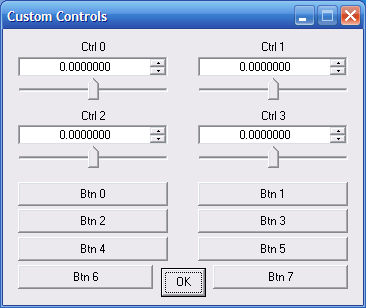
You can switch pages by clicking the button (Btn7) at the lower right of each page; on the main page it is labeled More Controls >>>.
Note that certain important controls appear on all pages, while others are on the first two pages, and some are only on one page.
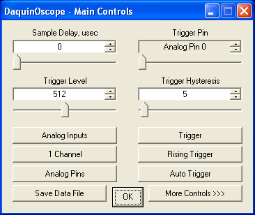
Main Controls:
Sample Delay:
The Sample Delay control appears in the same place (Ctrl0) on all dialog pages. It adds an adjustable delay after each sample to reduce the effective sample rate. The actual measured sample rate in Hz is shown via a separate floating resizeable Sample Rate display. The displayed rate is also used to automatically update the Daqarta time (X) axis. In general, you can blindly adjust Sample Delay until you get a desired sample rate or waveform display.
The Sample Delay is applied after all requested channels per sample, and the measured sample rate is likewise the overall sample rate. For analog inputs with Sample Delay set to 0, this means that each 2-channel sample time point takes approximately twice as long to acquire as a single channel, resulting in about half the number of 2-channel samples per second. For 4 channels the overall rate is about 1/4 the single-channel rate.
As Sample Delay increases, it begins to dominate the overall sample time, so there is less difference between 1, 2, and 4 analog channels.
Note that the number of Digital channels has no effect on sample rate, since 8 channels are always sampled internally and then only the selected channels are displayed.
Using default settings for other controls, the following sample rates were obtained for various sample delays:
Sample  -------- Analog --------      -- Digital 1-8 Ch --
Delay    1 ch     2 ch     4 ch       Mode 0,3    Mode 1,2
  0     104618    47302    24270       428094     386707
  1      93601    45862    23801       317618     293578
  2      85906    43866    23214       240828     226749
  5      68303    38589    21724       139434     134737
  10     50723    32315    19554        81920      80301
  20     33516    24409    16385        44920      44421
  50     16678    14054    10950        19066      18976
  100     9067     8229     7059         9732       9709
  200     4743     4501     4128         4917       4911
The above default Analog sampling is set to 8 bits, and uses a 2 MHz ADC Clock. These are set via controls at the lower left of the "Oscillators and Misc" controls page. Setting 10-bit sampling will reduce sample rates, as will slower ADC Clock settings. (See ADC Clock for details.)
It is also possible to use interrupt-driven sampling, but only at much lower overall sample rates (below 30 kHz or so). See the "Oscillator Interrupt Rate" and "Interrupt Lock" control topics on the same "Oscillators and Misc" controls page.
Trigger Pin:
The Trigger Pin control (Ctrl1) only appears on the Main Controls dialog page, where it allows selection of the source for triggered operation. You should always set the desired source before toggling the Trigger button on (Btn1), especially if the Auto / Normal Trigger button Btn3) is in Normal Trigger mode. The reason is that if there is no triggerable signal on the selected line, Normal Trigger will wait until one arrives... which may never happen. Auto Trigger mode will wait for the Auto-Trigger Wait interval (Ctrl2 on the Trigger Timing page), which defaults to 1 second per trace update.
The Trigger Pin control looks like an edit type, but you can't actually enter anything into it. Instead, use the slider or the small up/down buttons to move through the options, which will be shown in the control window.
The selections are Analog Pin 0 through Analog Pin 5, then Digital Pin 2 through Digital Pin 13, then Wave Osc 0 if it is in use.
As indicated in the Introduction, you can use digital signals to trigger analog acquisition, or analog signals to trigger digital acquisition.
Trigger Level:
The Trigger Level control (Ctrl2) only appears on the Main Controls dialog page. It only applies to triggering from an analog source. If Trigger Hysteresis (Ctrl3) is set to 0 and Rising Trigger (Btn3) is selected, then when the raw ADC value (0-1023) of the incoming analog source rises above Trigger Level, a trigger event is detected. If Falling Trigger is selected, then the source must fall below Trigger Level.
Note that trigger level is always specified over a 10-bit range, even if the main data acquisition is only 8-bit. If you want to trigger on a specified 8-bit level you need to multiply the value by 4 before entering here.
Trigger Hysteresis:
The Trigger Hysteresis control (Ctrl3) only appears on the Main Controls dialog page. As with Trigger Level, it only applies to analog trigger sources, and is likewise in raw ADC steps but is limited to 0-255.
When set to any value above zero, Trigger Hysteresis works with Trigger Level to provide a two-threshold trigger system that is noise-resistant.
Trigger Hysteresis is added to Trigger Level to form an upper limit, and subtracted from it to form a lower limit. With Rising Trigger, the trigger source must start below the lower threshold and rise through the upper threshold before a trigger event is detected. With Falling Trigger the order is reversed.
See the main Daqarta Trigger Hysteresis topic for an extended discussion of the general principles.
Analog / Digital Inputs:
The Analog / Digital Inputs button (Btn0) appears on the Main Controls and Trigger Timing dialog pages. It toggles between analog-only and digital-only input modes. This only applies to signal display, not to trigger sources... you can have digital triggering for Analog signals, or analog triggering for Digital signals.
When in Analog mode, the Channels button (Btn2) below it can be toggled between 1, 2, and 4 channels. Btn4 below that will be labeled Analog Pins and will allow selection from among the 6 avaiable analog channels of the Arduino.
When Btn0 is in Digital mode, the Channels button can be toggled between 1, 2, 4, and 8 channels, and the button below it will be Digital Pins.
Trigger Toggle:
The Trigger button appears in the same place (Btn1) on all control pages. When toggled on the trigger system is activated, such that data collection waits until a trigger event is detected on the selected Trigger Pin before collecting and displaying 1024 samples. If the trigger mode is set to Auto Trigger (default) and no trigger event is detected before the Auto-Trigger Wait elapses (1 second default), then data collection begins regardless. If the trigger mode is set to Normal Trigger then it will wait indefinitely.
The above assumes that Trigger Delay (Ctrl1 on the Trigger Timing dialog page) is set to 0 (default). Positive delay values mean that data collection waits that many microseconds before collection begins. (Negative values are allowed, with certain limitations, allowing you to view events before the trigger. See the Trigger Delay topic for a full explanation.)
Trigger action is also affected by Trigger Holdoff (Ctrl3 on the Trigger Timing dialog page), which is the minimum time between trigger events. This is useful for signals like repeating tone bursts. See the topic for more information.
1,2,4,8 Channels:
The Channels button (Btn2) appears on the Main Controls and Trigger Timing dialog pages, and sets the number of input channels to be sampled. Clicking this button advances from 1 Channel to 2 Channels to 4 Channels and back to 1 Channel, if the button above it (Btn0) is set to Analog Inputs.
If Btn0 is set to Digital Inputs, then the repeated clicks of the Channel button advance through 1, 2, 4, 8 and back to 1.
In either case, holding down the SHIFT key while clicking the button will decrease the number of channels, until eventually wrapping back to the maximum.
Note that increasing the number of channels causes the Y axis display to increase as well. For example, with a single channel the default display runs from 0 to 5V. With 2 channels it runs from 0 to 10V, with the second channel running from 0 to 5 and the original single channel shifted up to run from 5 to 10. With 4 channels the range is 0 to 20, with the 4th channel from 0 to 5, the 3rd from 5 to 10, the second from 10 to 15, and the 1st from 15 to 20.
These channel positions are set by DaquinOscope via the main Daqarta Individual Adjust controls in the Zero dialog, as well as overall Display Magnification. Changing the Zero settings will give erroneous axis readings, but the cursor readouts will be correct. Changing the magnification (via PgUp or PgDn keys) may drive the intended channel off the screen, but again will not affect the readouts.
In addition, with Analog Inputs the X axis changes when Channels changes. There are two factors at work here: First, the Arduino has only a single ADC to acquire analog data, so for multiple channels it must "multiplex" them by switching to each in turn and reading it separately. At the fastest speeds (no Sample Delay) it thus takes about twice as long to read two channels as one, and four times as long to read four.
Note that this multiplexing causes "channel skew", where the channels are not actually sampled simultaneously, but are displayed as if they were because the different sample times are lost. This can cause mistaken conclusions about whether events are simultaneous, or which one came first.
The second factor is due to the limited 2048-byte working memory of the Arduino Uno, which after allowing for other working variables only has room for 1024 total ADC data values. If Channels is set to 2, there is room for only 512 samples of 2-channel data; at 4 channels, only 256 samples. So DaquinOscope reduces the displayed samples (via the main Daqarta X-Axis eXpand control) so they just fill the display in each Channels mode.
The X-axis display is thus adjusted to account for both of the above factors. (There is no such Digital Inputs change, nor channel skew, since all 8 channels are always sampled simultaneously and fit into a single byte.)
IMPORTANT: If you use Daqarta's Spectrum mode to view 2 or 4 analog channels, please note that the spectrum of each channel is always computed with a full 1024 samples. When using 2-channel mode, with only 512 actual data samples per channel, 512 null samples appended to each before computing the spectrum. Likewise, with 4 channels having only 256 actual data samples each, 768 null samples are appended.
This gives less overall energy reported at every frequency due to the last half or 3/4 of the data being nulls. For a more accurate spectrum make sure Spectrum Window is active, then set Spectrum Width to 512 for 2 channels or 256 for 4, and finally make sure that the small offset button to the right of Width is toggled to '<' to align the window with the start of the data. (The default is 'o' for a centered window.)
Please read the Window Width and Peak Operation subtopic under Spectrum Window Width if you want to use Peak or Track modes.
Rising/Falling Trigger Slope:
The trigger slope button (Btn3 on the Main Controls and Trigger Timing dialog pages) toggles between Rising Trigger (default) and Falling Trigger. In Rising mode, an analog source (selected by the Trigger Pin control) must rise through the Trigger Level from below. In Falling mode it must fall through from above.
With digital sources Trigger Level is ignored. In Rising mode a trigger event happens on a rising edge, where the digital input pin rises from 0 to 1. (There is actually a threshold that is typically about halfway between 0 and 5 volts, but it is not a precise value.) In Falling mode, a change from digital 1 to 0 causes a trigger event.
Analog/Digital Pins:
The Analog/Digital Pins button (Btn4) appears on the Main Controls and Trigger Timing dialog pages. Although the 1,2,4,8 Channels button (Btn2) controls the number of channels, this Analog/Digital Pins button allows you to specify which channels to use.
Clicking this button opens a Wait Buttons Button Select dialog that allows selection of any 4 channels. If Btn0 is set to Analog Inputs then this button will be Analog Pins; you can select from ADC Pin 0 to ADC Pin 5, with 0-3 default:
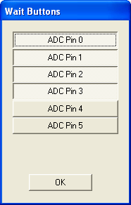
The buttons you select do not need to be sequential; you can (for example) select 1, 3, 4, and 5.
Selections do not take effect until you click the OK button at the bottom of the Wait Buttons dialog.
If 1 Channel is set on Btn2, then the uppermost selected button will be displayed. For 2 channels, the upper 2 selected buttons will be used.
Things are slightly more complicated if Digital Inputs is set on Btn0. Only 8 digital pins can be used at one time, but the Arduino Uno has 13 pins, including pins 0 and 1 which are dedicated to the serial port. Pins 14 and 15 are not physically connected, but are present internally.
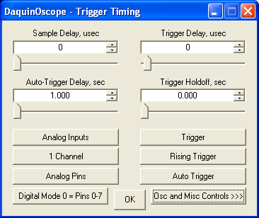
To allow access to all pins, DaquinOscope allows selection of Digital Mode on Btn6 of the second page of controls, labeled DaquinOscope - Trigger Timing and found by clicking the More Controls >>> button (Btn7) at the lower right of the main dialog.
With the default Digital Mode 0 = Pins 0-7, the Digital Pins button will show only those pins. Here are the Digital Pins buttons for each of the modes:
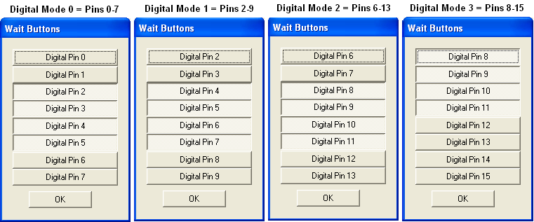
As with Analog Pins, you only select 4 pins in the Digital Pins dialog, and they don't need to be sequential. The uppermost selected pin is used for 1 Channel, the upper 2 for 2 Channels, and the upper 4 for 4 Channels. All 8 pins are used in 8 Channels mode, regardless of whether they are selected.
Auto / Normal Trigger:
The Auto / Normal Trigger button (Btn5 on the Main Controls and Trigger Timing dialog pages) defaults to Auto Trigger but can be toggled to Normal Trigger. If the main Trigger button is active, Normal Trigger waits for a valid trigger event before updating the display, such that the Trigger Pin signal meets the specified Trigger Level, Trigger Hysteresis, Rising / Falling Trigger, Trigger Delay, and Trigger Holdoff specifications. If a valid trigger event never arrives, the display is never updated.
Auto Trigger likewise waits for a valid trigger event with the same specifications, but if one doesn't arrive within Auto-Trigger Wait seconds (Ctrl2 on the Trigger Timing dialog page) the display is updated with current input channel data regardless. It will not be synchronized with anything, but you will at least be able to see what's there.
Even if you plan to ultimately use Normal Trigger, you should consider starting out with Auto Trigger until you see that you are getting the desired triggering action. If you start out with Normal, and you don't see any display updates, it can be hard to determine the problem: The input signal may have become disconnected, or it may have dropped below the Trigger Level threshold, or you may have set Trigger Pins to the wrong channel, etc. With Auto, you can easily troubleshoot the problem.
Save Data File:
Clicking Save Data File (Btn6 on the Main Controls dialog page) saves the data used to create the current display to a .DQA file, which is Daqarta's extended .WAV format. It preserves X and Y calibration data that Daqarta will use to show the original voltages and times on subsequent viewing of the file, along with any Notes that were made before clicking Save Data File.
You could use the "Save trace as DQA data file" in the main Daqarta File Menu, but that only works for 1, 2, or 4 channels... not the 8 channels available in Digital mode. Save Data File will save these properly, and Daqarta will later be able to open the file with the normal DD/Open button in the toolbar, or the Open Existing option in the File Menu.
One possible advantage of using "Save trace as DQA data file" in the File Menu for 1 or 2 channels is that it will also save main Daqarta Generator or Input channels from your sound card, along with the DaquinOscope channels, as long as they don't conflict with the Display Channels buttons at the lower left of the main Daqarta display area.
For example, with a single DaquinOscope channel active it will replace the former L.In button with Ch0, and be displayed in yellow (default color). That means that R.In, L.Out, and R.Out are still free to show the right Input and both Left and Right Generator channels normally, which will be saved along with the DaquinOscope Ch0.
On the other hand, if you display 2 DaquinOscope channels they replace both L.In and R.In channels with Ch0 and Ch1, leaving only L.Out and R.Out free for Generator signals. With 4 DaquinOscope channels there are no main Daqarta channels available for display or saving.
You will also need to use "Save trace as DQA data file" for Averager data, whether for DaquinOscope or mixed main Daqarta channels.
(Another feature of using "Save trace as DQA data file" for 1, 2, or 4 channels is that the file will subsequently appear in Recent Files; that doesn't happen when using the Save Data File button.)
Please note: The Direct-to-Disk DDisk option will not allow continuous data collection of DaquinOscope data, only sound card data. That's because the Arduino must send data over the slow USB serial port; continuous data would be limited to sample rates in the 10 Hz range. DaquinOscope gets around this by collecting 1024-sample data bursts at high speed, then sending the data back to Daqarta in a separate burst during which no incoming data can be collected. This mimics the way a hardware oscilloscope behaves with real-time data, since you couldn't view a continuous stream anyway... it has to be "frozen" in screen-sized bursts or you'd only see a blur. (You might still see only a blur, with DaquinOscope or a hardware scope, unless you have the trigger set correctly.)
After opening a saved file, Daqarta can only display 4 file channels at a time, but for 8-channel files the Display Channels buttons at the lower left of the display are labeled Ch0-Ch3 (default) and Up/Down arrows will appear to their right, allowing display (and cursor readout) of any 4 adjacent channels, from Ch0-Ch3 to Ch4-Ch7.
If you use software other than Daqarta to view DaquinOscope files, you will need to manually change the extension from .DQA to .WAV after the recording. You will lose the X and Y calibration that is included in the .DQA format, but the waveforms will be intact.
Alternatively, if you don't need 8-channel Digital files and you don't need X and Y calibration, you can use the other main File Menu options to save as .WAV, .DAT, or .TXT.
The default Save Data File name is "Dscope.DQA", which you can change by replacing the "Dscope" quoted string in the Str1="Dscope" line near the start of the DaquinOscope macro code. Note that the .DQA extension will be added automatically during the save.
You can also change the filename via the normal Windows Save As dialog that appears when you click the Save Data File button.
If you want the file names to form an ever-increasing series, such as Rat000, Rat001, etc., you can go to the main Daqarta File menu and toggle "Auto-Increment Filenames" on (a check mark will appear at the left). You can toggle this on or off any time while DaquinOscope is running.
Alternatively, you can modify the DaquinOscope macro code to always auto-increment, regardless of the main File menu Auto-Increment state, or to never auto-increment. Locate this line near the start of the code:
UF=2 ;Auto-increment DATA file name
Change the value of UF as needed:
UF=0       ;Never auto-increment
UF=1       ;Always auto-increment
UF=2       ;Use main Auto-Increment state
More Controls Button:
Clicking Btn7 advances the dialog to the next page. On the default page this button is labeled More Controls >>> and the page title is DaquinOscope - Main Controls. One click advances to the DaquinOscope - Trigger Timing page title, while the button itself changes to Osc and Misc Controls to indcate that if you click it again the dialog will advance to DaquinOscope - Oscillators and Misc. On that page, the button will show Main Controls to indicate that a third click will return to the default page.
Note that if you hold down the SHIFT key while clicking this button, the dialog will go back to the prior page in the cycle. If you are on the default page, it will go to DaquinOscope - Oscillators and Misc.
Trigger Timing Controls:
To reach the Trigger Timing dialog page starting from the default Main Controls page, click the More Controls >>> button (Btn7) at the lower right corner of the page.
Trigger Delay:
The Trigger Delay control (Ctr1, only on the Trigger Timing dialog page) sets the delay, in microseconds, that elapses between arrival of a trigger event and the start of data collection for the next display update.
Positive Trigger Delay allows you to move the 1024-sample display "window" later in time, up to 32767 microseconds. This lets you examine events that arrive more than 1024 samples after a trigger event, which at high sample rates can be a rather short time. For example, at a typical single-channel Analog sample rate of 104618 Hz with Sample Delay at zero, the display shows less than 10 milliseconds of data. (1024 / sample rate.) With Digital inputs it could be less than 2.5 msec.
If your region of interest is later than that, you could widen the window by increasing Sample Delay to reduce the sample rate, but at the expense of resolution. That would be like using lower-power binoculars to view a scene... more things may be in view, but smaller and harder to resolve. With Trigger Delay, on the other hand, you can pan across the scene at full high-power resolution.
Sometimes you may want to see what happened before the trigger event. To accomplish this, DaquinOscope acquires data continuously into a 1024-sample circular buffer while waiting for a trigger event. When the event is detected, the Trigger Delay setting (in samples now, instead of microseconds) specifies how far back in the buffer to start when sending data to Daqarta for display.
For example, if you set Trigger Delay to -100, the Ctrl1 label will be NEG Trigger Delay, samples instead of Trigger Delay, usec. The desired display region will be from -100 to +923 samples instead of the usual 0-1023. The circular buffer starts filling while awaiting the trigger event. Suppose it is at buffer position 500 when the trigger event is detected. This means that the position 400 will correspond to the -100 Trigger Delay setting, and 400 + 1023 = 1423 will be the last sample acquired. The buffer actually holds only 1023 samples, after which it fills starting from position 0 up to 399 (400 samples) and then stops just before overwriting sample 400 (the desired -100 equivalent). Then the collected data is sent to Daqarta starting with samples 400-1023 followed by 0 to 399. The X axis is automatically adjusted to show the location of the trigger event at 0 time, with prior data shown at negative times.
The above example is for Analog Inputs with Channels set to 1, or for Digital Inputs. For 2-channel analog inputs, the maximum negative delay is -511 samples, and for 4-channel analog inputs it is -255 samples.
Please note: To allow negative Trigger Delay, you must be either in Digital Inputs mode, or Analog Inputs with ADC Bits (Btn6 of the Oscillators and Misc dialog page) set to 8 (default). You can not use 10-bit ADC Bits for this.
Also, you can not use Interrupt Lock with negative Trigger Delay. The delay will automatically be forced to 0 if it is negative when interrupts are toggled on, and the control will only accept positive values.
Important: With Analog Inputs, negative Trigger Delay requires that the Trigger Pin be set to one of the analog channels being displayed. If not, the first (lowest-numbered or top-screen) channel will be used by default.
With Digital Inputs and negative Trigger Delay the Trigger Pin requirements are more relaxed, in that you can use any digital pin as a trigger, even if it is not being displayed.
In no case can you use analog Trigger Pins with Digital Inputs, nor digital Trigger Pins with Analog Inputs when using negative Trigger Delay.
Note that for Analog Inputs there is a slight sample rate decrease with negative Trigger Delay, compared to 0 or positive delay. The reason is that for negative delay the trigger conditions must be tested on every sample, which adds a small delay to each sample interval. For 0 or positive delay all trigger testing happens before the start of sample collection, which then runs with no added sample delay.
Auto-Trigger Wait:
The Auto-Trigger Wait control (Ctr2, only on the Trigger Timing dialog page) sets the maximum time, in seconds, that Auto-Trigger mode will wait for a trigger event. If no event is found, data collection proceeds anyway and the display is updated without being synchronized with anything. See the Auto Trigger subtopic for more info.
Auto-Trigger Wait may be set between 10 msec and 32767 seconds. The default is 1 second. In general, you should make this value somewhat longer than the longest expected time between triggers, but not by much. Note that when DaquinOscope is waiting for a trigger the system is unresponsive. If you set the wait time too large, you may get tired of waiting... just as you would in Normal Trigger mode instead of Auto Trigger.
Trigger Holdoff:
The Trigger Holdoff control (Ctr3, only on the Trigger Timing dialog page) sets the minimum interval between triggers, in seconds, and defaults to 0.
Non-zero Trigger Holdoff is useful for signals like repeating tone bursts, where you want to trigger on the start of each burst, not on some arbitrary cycle of the waveform within the burst. Without Holdoff, any one of the cycles in a burst might be an acceptable trigger.
Trigger Holdoff is usually used with Normal Trigger mode, unless you are sure that the burst repeat period is less than the Auto-Trigger Wait time. Then you can use Auto Trigger mode.
The display will not be stable until Holdoff is properly set, but you should be able to see signal bursts rolling past. For Analog Inputs set Trigger Level to a value about half that of the visible peaks. The display still won't be stable, but at least it should always start at the same vertical extent of the waveform. (This is not an issue with Digital Inputs.)
The Holdoff value must be shorter than the overall burst repeat cycle by at least one cycle of the carrier frequency (the waveform that appears during a burst). It must also be at least as long as one burst (less one carrier cycle).
If you know the burst duration, set Holdoff to that value. (Note that for Holdoff purposes, the relevant duration is actually the time the burst exceeds the Trigger Level, not the overall burst duration. This is usually only an issue for bursts with slow rise and/or fall times.)
If the burst duration is variable, set Holdoff to the maximum value. If the repeat cycle is variable, set Holdoff less than the lowest repeat cycle.
For example, suppose you have a 500 Hz tone burst that varies between 10 and 15 msec, and the overall repeat cycle varies between 40 and 60 msec. One cycle of the 500 Hz carrier is 1/500 = 2 msec. Holdoff must be greater than (15 - 2) and less than (40 - 2) msec.
If you are not sure of the durations involved (which may be the case if you are not controlling them yourself, and you can't get a stable trigger to view them until Holdoff is properly set), then take a guess. You should deliberately make your guess a little too high or too low. If you start with a low value, slowly increase it until you get a stable display. If you start with a high value, slowly decrease it.
If the burst durations or repeat cycle times are variable, the display may seem to be stable for a while, then roll when the duration becomes too long or the repeat cycle too short. If so, keep changing Holdoff in the same direction until the display remains stable. If you go too far and it becomes unstable again, back off to a medium value.
Digital Mode:
The Digital Mode button (Btn6, only on the Trigger Timing dialog page) sets the range of pins used for Digital Inputs. There are 4 modes, reachable by repeated clicks as needed:
    Digital Mode 0 = Pins 0-7  (default)
    Digital Mode 1 = Pins 2-9
    Digital Mode 2 = Pins 6-13
    Digital Mode 3 = Pins 8-15
Modes 0 and 3 are slightly faster than modes 1 and 2 because each uses a single port on the Arduino processor. (PORTD for Mode 0 and PORTB for Mode 3.) Unfortunately, each of these modes only accesses 6 useful pins instead of 8. That's because Pins 0 and 1 in Mode 0 are committed to the serial port, and Pins 14 and 15 in Mode 3 have no external connections.
Modes 1 and 2 are slower because they must access both PORTD and PORTB and combine the results to get the indicated 8 active pins.
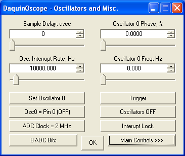
Oscillators and Misc. Controls:
To reach the Oscillators and Misc. Controls dialog page starting from the default Main Controls page, click the More Controls >>> button (Btn7) at the lower right corner of the page to get to the Trigger Timing page (at which point the button becomes Osc and Misc Controls >>> to indicate what comes next), then click it one more time. The button will then be labeled Main Controls >>>, and the dialog title will be DaquinOscope - Oscillators and Misc. as shown:
Oscillator Overview:
DaquinOscope supports up to 4 independent oscillators, whose outputs may be used to drive external systems that are monitored by DaquinOscope's conventional oscilloscope functions.
Please note, however, that the oscillators use Arduino interrupts to control their sample rate, unlike the default Sample Delay timing used for input acquisition. The oscillator interrupt is generated by a hardware timer at a programmable rate set via the Osc. Interrupt Rate, Hz control, and all active oscillators are updated on each interrupt. This only takes a small amount of time, but it will interfere with the independent (hence unsynchronized) Sample Delay timing to cause jitter in the acquired input data.
To avoid this, DaquinOscope provides an Interrupt Lock button that forces input acquisition to also use the oscillator interrupt, instead of the Sample Delay, keeping everything synchronized. This will require much lower sample rates than the default Sample Delay system allows. See the Interrupt Lock - Rate Limits subtopic and especially Freeze-Up Recovery for more information.
All 4 of the oscillators (Osc0 - Osc3) may be square wave types, each having its output on its own selected digital Pin 2-13. (Note that Pin 13 is also connected to the Arduino's onboard LED.)
Alternatively, the 0th oscillator (Osc0) may use Pins 2-9 wired to a simple 8-bit R-2R ladder DAC to produce an arbitrary analog waveform, such as a sine wave, using a 256-step or 1024-step wavetable. (Note that the 1024-step table uses the same memory otherwise used by the oscilloscope data acquisition functions, so DaquinOscope is then no longer a "scope" but a dedicated oscillator... DaquinOsc?)
There are individual Phase and Frequency controls for each of the oscillators, accessible by toggling the Set Oscillator0 button (Btn0 on this page only) as needed. The button below that defaults to Osc0 = Pin 0 (OFF), and opens a dialog that allows you to set the digital output pin for that oscillator.
All oscillators employ phase accumulator methods to allow extremely fine frequency resolution using a constant output sample rate, set by the Osc. Interrupt Rate, Hz control (Ctrl2, on this page only). The square oscillators have a resolution of one part in 2^25, so at the default 10000 Hz sample rate the resolution is 10000 / 2^25 or 0.000298 Hz (298 microhertz). The wavetable oscillator (either 256- or 1024-step table) has a resolution of one part in 2^32, or 0.00000233 Hz (2.33 microhertz).
The frequency of each oscillator is set via the Oscillator N Freq, Hz control, where N is 0-3 as selected by the Set OscillatorN button. The lowest frequency that can be created is the same as its resolution at the given sample rate (0.000298 Hz for square, and 0.00000233 Hz for wavetable) as discussed above. (Compare to the Arduino's native tone() function, which can go no lower than 31 Hz.)
The maximum oscillator frequency is half the sample rate. This will be fine for square waves, which only need two samples per cycle. For wavetable oscillators you will need many more samples per cycle, depending on how closely you want the output to approximate the target wave shape.
Please note that the frequency control computes internal values based upon the current Osc. Interrupt Rate, Hz at the time the frequency is set. If you later change the interrupt rate, the actual output frequency will change proportionally, but the displayed Oscillator N Freq control will not change. So, you should always set the interrupt rate first, before setting any oscillator frequencies.
Free-Standing Arduino Oscillators:
When you close DaquinOscope (using the OK button or the [X] in the dialog title bar), it normally turns off the oscillators and their associated interrupts. Otherwise, they would keep running as long as the Arduino had power, and might interfere with the next application such as the DC_Chart_Recorder.
If you want to keep the oscillators running, comment out this line near the end:
Port=$(hF0) + "F" + $(hC0) ;Set Oscs (and ints) off
Then run DaquinOscope and set the oscillators as desired. Close DaquinOscope, and they will continue as before. If you have an external power supply for the Arduino, you can disconnect the USB cable from the computer to get a free-standing oscillator or set of oscillators.
This may be especially useful with a wavetable oscillator that is set to produce a continuous test schedule or a flashing LED sequence, for example.
Square Wave Jitter:
The phase accumulator method, when used for square waves, can result in a certain amount of cycle-to-cycle jitter, even though the average frequency is very accurate. (See the "Edges - Snap vs. Interpolate" subtopic under the Square Wave topic for the main Daqarta Generator for a discussion. DaquinOscope square wave oscillators use the "Snap" method.)
The jitter arises at any square wave frequency that is not an exact power of 2 divided into the sample rate. For the 10000 Hz default rate, dividing by 2, 4, 8, 16 and 32 gives 5000, 2500, 1250, 625, and 312.5 Hz respectively. The lowest possible jitter-free frequency would be with a divisor of 2^25, for a frequency of 0.000298023 Hz (equal to the frequency resolution), or a period of 3355.443 seconds or 55.92 minutes.
However, frequencies which are any even integer divided into the sample rate are much better than odd or non-integer values. For example, 1000 Hz (sample rate / 10) gives a very slow jitter, with a frequency of 0.0003 Hz or a period of 3355 seconds (55.9 minutes). On the other hand, 440 Hz has a jitter frequency of 165 Hz, or a period of only 6 msec!
Below is a table of even divisors up to 32, with the associated frequencies and jitter periods. (The perfect jitter-free values show periods of ******* to represent an infinite period.)
Note that the frequencies listed are those actually generated, which don't exactly match the results of the division because of the above-mentioned 298 microhertz frequency resolution of the phase table method. So instead of 10000 / 10 = 1000, the table shows 999.999940395 Hz... an error of 60 parts per billion. (Note that this presumes the Arduino clock generator is exactly its nominal value of 16 MHz; in reality it is probably much worse than 60 ppb.)
Div    Frequency         Jitter period, sec
2      5000.000000000    *******
4      2500.000000000    *******
6      1666.666567326    3355.443
8      1250.000000000    *******
10      999.999940395    3355.443
12      833.333432674    1677.722
14      714.285671711    3355.443
16      625.000000000    *******
18      555.555522442    3355.443
20      500.000119209    838.861
22      454.545319080    671.089
24      416.666567326    838.861
26      384.615361690    3355.443
28      357.142984867    559.241
30      333.333313465    3355.443
32      312.500000000    *******
You can use the Jitter_Tbl macro included with Daqarta to generate longer tables, with other sample rates than 10000 Hz. This may allow you to optimize for certain oscillator frequencies.
The actual jitter frequency and period will be displayed on a pop-up message window when you enter or change the value of any square wave oscillator.
See the Oscillator Interrupt Rate and Oscillator N Frequency control subtopics below for more information.
Wavetable Oscillators:
DaquinOscope wavetable oscillators use a circular phase accumulator that consists of an ordinary 32-bit value. At each output sample, a frequency-specific constant value is added to the accumulator and the result is used as an address into a 256- or 1024-step wavetable. The 256-step oscillator uses the uppermost 8 bits as the address into the wavetable, while the 1024-step oscillator uses the upper 10 bits.
The 8-bit value that is read from that address is then sent to the 8 output pins (Digital Pins 2-9) to produce 8-bit waveforms, typically using a simple R-2R ladder DAC. (See Wavetable DAC Construction, below.)
The 256- or 1024-step wavetable oscillator thus requires a table file with 256 or 1024 8-bit values. DaquinOscope makes it easy to provide this table by allowing you to select any Daqarta Arb file of any length, and automatically scales it to fit. Daqarta includes a library of many common and not-so-common waveforms, and you can create your own custom files using the Arb_From_Equation or Arb_From_List macro mini-apps, or from a text file of values.
To load the wavetable file, or to replace one already loaded, make sure that the Set OscillatorN button is toggled to Set Oscillator0. Then click on the Osc0 = Pin N and enter 14 for a 256-value file or 15 for a 1024-value file. (Note that only the 256-value file will allow simultaneous data acquisistion.)
A Windows file Open dialog will appear, showing all the files of .DAT type in the Daqarta - User_Data folder. Those that start with Arb_ are the included library files, described in the Arb_From_Equation topic.
After choosing a file, but before you can toggle to Oscillators ON, you'll need to enter a value for Oscillator 0 Frequency, Hz. This control assumes that the file holds exactly one cycle of the desired waveform, such that the output frequency will be the number of complete passes through the file per second. (Make sure you have set the desired interrupt rate first.)
Here's an example of the 256-step output waveform when using the Arb_Sine file with a DAC made of 10K and 20K standard 5% tolerance 1/4 watt metal film resistors. (1% tolerance was also tested and gave no measureable improvement in distortion.)
The Interrupt Rate was 40 kHz, and the
Oscillator 0 Freq was set to give exactly one cycle in
the 1024 samples of Daqarta display width:
40000 / 1024 = 39.0625 Hz. Note that this waveform was
acquired with the ADC in 8-bit mode (at the default 2 MHz ADC
Clock setting), so this is an 8-bit output viewed on an 8-bit
input:
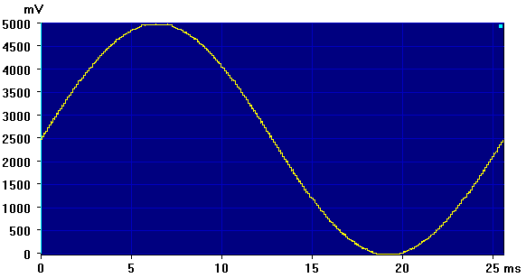
The slight flat spots at the high and low points are due to the auto-scaling of Arb_Sine from 16-bit to 8-bit resolution for DaquinOscope. These can be reduced or eliminated by using Arb_From_Equation to create a sine wave with slightly reduced amplitude factor K. Reducing it from 32767 to 32000 will eliminate the flats but give a wave with slightly less than full-scale output, while 32250 will just barely reach full scale at the peaks. But these are basically cosmetic changes that have no effect on measured distortion.
Increasing the frequency to 1000 Hz and switching Daqarta to Spectrum mode we see that there is indeed a fair amount of distortion. (But note that a "perfect" 8-bit DAC would have a similar amount, simply due to the low number of bits.)
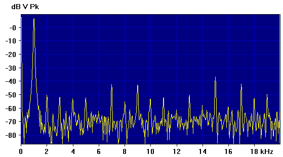
The big DC component seen in the spectrum is due to the fact that this sine wave runs between 0 and 5 volts, not symmetrically about 0. The spectrum shows this as the equivalent of a +/-2.5 V sine riding on a +2.5 VDC baseline. (Note that 2.5 V is 20 * log10(2.5 / 1.0) = +7.96 dB above 1 volt, as indicated by the dB V Pk label. Toggling to Spectrum RMS mode would reduce everything by 3 dB, but the ratios would be the same.)
By using the Sigma mode of the cursor readouts we can measure the energy above 1500 Hz at about -30.5 dB, which relative to the +7.96 dB fundamental gives a THD+N distortion of 38.46 dB or about 1.2%. That's similar to the sine output of typical benchtop function generators. (Note that this is a "loopback" distortion measurement, so includes any distortion from the 8-bit Arduino ADC. But a separate measurement of the oscillator output using a 16-bit sound card with the THD_Meter macro mini-app found virtually the same result: 1.15% for THD+N and 0.82% for THD 25.)
It's possible to view the individual output bits by switching DaquinOscope from Analog to Digital. (You can do this even if you don't have a DAC.) By default this uses Digital Mode 0 to view pins 0-7, so toggle the More Controls >>> button at the lower right once so you see Trigger Timing in the title bar, then toggle the button at the lower left to Digital Mode 1 = Pins 2-9. Now toggle to 8 Channels:
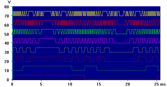
This hints at another application for a wavetable oscillator: It isn't limited to analog output via a DAC, but can be used to drive up to 8 digital lines with arbitrary test patterns. These lines could be used to drive stepper motor phases, LEDs, relays, or any other devices that use on/off signals.
You can set Oscillator 0 Freq to super-low values to get slow stepping through the sequence, if desired.
You don't need to use any standard waveform; you can enter a list of 1024 values to create your own custom Arb, using the method in Creating Arb .DAT Files From Text.
However, note that DaquinOscope is set to use standard Daqarta Arb files, which are 16 bits and 1024, 2048, 4096, 8192, or 16384 samples; it then converts them down to 256 or 1024 samples as needed. So if you only need 256 values for a custom Arb wavetable, you'll need to enter each one 4 times to get 1024 total. One trick to do this is to use a text editor that can handle columns; enter your 256 values in a single column, then copy it to make 4 columns.
If you need to use even less states in your test sequence, you can use the same trick to make 8, 16, 32, etc columns. For example, if you need only 128 values you'd make 8 columns for 1024 total values. When loaded for use as a 256-step wavetable, every 4th value would be used; you'd thus get two identical adjacent values instead of 8.
Note also that DaquinOscope is expecting 16-bit data, which it will convert to 8 bits by shifting right. You should thus left-shift your desired 8-bit values by 8 bits, padding with 8 zeros on the right.
You can enter values in hexadecimal format by preceding each with 'h', or in binary format by preceding with 'b'. So if you want to end up with a bit pattern of 11001010 you could enter it as b1100101000000000. In hexadecimal the same value would be CA so you'd enter hCA00.
Of course, you can use the DAC to create a single-channel analog test sequence using the same approach. Here you may find the Arb_From_List approach the easiest way to create simple test schedules, especially those that ramp linearly between values.
See the Free-Standing Arduino Oscillators topic above if you want the sequence to continue to run without DaquinOscope, or indeed without any computer attached.
Wavetable DAC Construction:
The Digital-to-Analog Converter (DAC) for DaquinOscope uses an "R-2R ladder" approach:
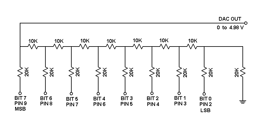
Note that the 9 lower (vertical) resistors are 20K each, twice the value of the 7 upper (horizontal) 10K resistors in the schematic. The exact values are not critical, but the 2:1 ratio is. You could just as well use 24K and 12K or 30K and 15K if you are using standard 5% tolerance values. (Use 1/4 watt metal or carbon film types, never carbon composition.) These 5% values will give decent results for many purposes, like a benchtop "function generator"; see the 1000 Hz spectrum image in the subtopic above. You might think that using 1% tolerance values would give better results, but tests showed no improvement in actual measurements, undoubtedly because this is only an 8-bit system.
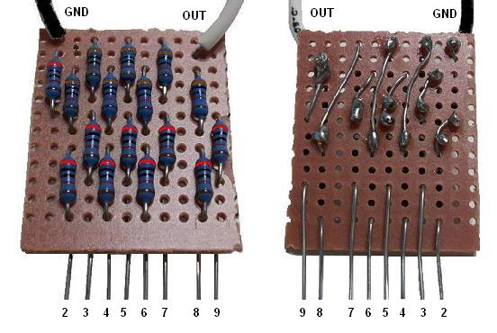
The board layout is shown below with the 20K resistors in pink. This is a view from the top (component side) of the board, with the copper traces on the bottom shown as if in an X-ray:
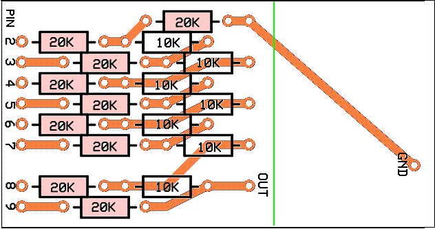
Note that the pin numbers on the layout have the LSB (pin 2) at the top and the MSB (pin 9) at the bottom, while the schematic has the MSB on the left and the LSB on the right.
Pay special attention to the sole 20K resistor on the top of the right side, which goes to ground. Other than this, all the 20K resistors are on the left (digital pin) side and all the 10K resistors are on the right.
The board layout assumes you will install it like a typical Arduino "shield", parallel to the Arduino board itself. Thus the ground connection is shown on the opposite header strip from the digital output pins. The resistor leads connected to the digital pins can be cut to plug directly into the header. Together with the ground lead this will support the shield above the Arduino. You can wire the OUT connection from the DAC to a separate connector or circuit as needed.
As an alternative, you can cut off the right side of the board (at the green line in the above image) and wire the ground to the 20K resistor it connects to, via the pad provided. Bend all the resistor leads that connect to output pins, making them parallel to the board, and trim so that you can stand the board on its edge and plug it into the digital header. Use hookup wire to connect the ground to an Arduino ground on either header.
The above image is not suitable for printing at the exact scale. Instead, the schematic and printable 600 DPI layouts are inclued in the Daquino_DAC_All600.PNG file that is installed with Daqarta in the Documents - Daqarta - Circuits folder.
Be sure to read the Notes section of Daqarta Printed Circuits before you begin.
You can use the printed layouts directly to create your own circuit boards, with either the laser printer toner transfer method, or with the direct-draw method discussed under Printed Circuit Construction.
Alternatively, you can edit the Daquino_DAC.PCB file in the same folder to make custom modifications first. See the PCB Files discussion in Daqarta Printed Circuits for the required software to use this file, and for information on how to submit it to have boards made by a 3rd-party supplier.
However, you don't really need any printed circuit board for this. The staggered placement of the the resistors was used to make it easy to wire this up on a 1.1 by 1.3-inch scrap of tenth-inch grid perfboard, using the resistor leads themselves to make all connections on the board. In this case the vertical (not shield) board orientation is recommended. The resistors whose ends will plug into the digital header can be secured with hot glue after construction to make a rigid assembly.
The image below shows the top and bottom views of the perfboard version. This used 1% tolerance resistors whose color bands don't show up very well in the photo, so the top band of each resistor was enhanced in this image. Bright red indicates 20K resistors, brown (all others) are 10K. Arduino pin numbers are shown, as are ground and output connections:
Oscillator N Phase:
The Oscillator N Phase control (Ctrl1 on the Oscillators and Misc dialog page only) defaults to Oscillator 0 Phase until the Set Oscillator0 button is toggled to another oscillator number.
The phase is set in percent of a full cycle, not in degrees. This forces the indicated oscillator phase accumulator counter to start at that specified point whenever the oscillators are started. (They are all re-started whenever you change any Phase setting, as well as when they are toggled on with the Oscillators ON / OFF button.)
Please note that Oscillator Phase is only relevant between two or more oscillators set to the same frequency.
Thus, if you have two oscillators running at 1000 Hz and one has its phase set to 25% while the other is at 0, the first one will always be 90 degrees (25% of a 360-degree cycle) ahead of the other. The other two oscillators may be set to 1000 Hz but with different phases, such as 50% and 75%.
Alternatively, you can set the other two to a different frequency, and they will track each other at whatever phases you set, independently of the first two oscillators.
Note that you must set oscillator frequencies before setting phases. Changing the frequency resets the phase accumulator of that oscillator to 0; it does not match the specified Oscillator Phase until a phase adjustment or an Oscillators ON / OFF restart.
Oscillator Interrupt Rate:
The Oscillator Interrupt Rate control (Ctrl2 on the Oscillators and Misc dialog page only) defaults to 10000 Hz. This is the sample rate for all oscillators, and is also used as the sample rate for analog and digital inputs when the Interrupt Lock button (Btn5) is active.
The Interrupt Rate is based on an internal timer running at 2 MHz, divided by a value N from 40 to 256. The lowest rate is 7812.5 Hz when N is 256, and the upper rate is 50000 Hz when N is 40. You don't have to know anything about this divisor when using the control, except to be aware that the frequency you enter will be converted to the nearest valid frequency. Most of these will not be convenient values. The table below shows typical "nice" rates, and the N divisors used internally to get them:
     Hz        N
    50000       40
    40000       50
    25000       80
    20000      100
    12500      160
    10000      200
     8000      250
If you enter other values, the actual frequency will be shown. DaquinOscope computes it essentially by dividing it into 2 MHz, rounding the result to the nearest integer, and dividing that into 2 MHz. So if you enter (say) 15000 Hz, then 2000000 / 15000 = 133.3333, which is rounded to 133, and 2000000 / 133 gives an actual frequency of 15037.594 Hz.
There is normally no reason to avoid these other values, since DaquinOscope will use the actual sample rate to set the Oscillator frequency. Likewise, when Interrupt Lock is active to set the input sample rate, the display X axis will be automatically adjusted to reflect the true time base.
Normally, you should always set the sample rate before you set frequency and/or phase. However, once they are set for a given sample rate, changing the rate will change all output frequencies by exactly the ratio of the change, while keeping the same phase relationship. For example, if you set everything initially at a 10 kHz rate, changing it to 20 kHz will exactly double all the frequencies. Note, though, that the Oscillator N Frequency display will not change when you change the rate.
As noted earlier, the sample rates can only change to specific values; you can't (for example) set 30 kHz to triple the 10 kHz frequencies. But you can get a triple if you pick the right starting rate. Consider that the sample rate is 2 MHz divided by a value N. If you want to triple the rate, then the initial N should be 3 times the final N. For example, if the final sample rate is to be 40 kHz the N would be 50 as shown in the above table. So you need to set an initial rate with a value of 3 * 50 = 150. The rate to set would thus be 2 MHz / 150 = 13333.333 Hz.
Oscillator N Frequency:
The Oscillator N Frequency control (Ctrl3 on the Oscillators and Misc dialog page only) defaults to Oscillator 0 Frequency until the Set Oscillator0 button is toggled to another oscillator number.
The frequency is set in Hz. As noted in the Oscillator Overview section, the oscillators use a phase accumulator technique to achieve high resolution. The resolution is the reciprocal of the accumulator counter size C, which is 2^25 for square oscillators, or 2^32 for the wavetable oscillators.
When you enter a value, the closest achievable value is actually used and displayed. If the entered value is Z Hz and the Interrupt Rate is S, then the phase step size US is
US=C * Z / S
The actual frequency F is then
F=US * S / C
This is displayed with 5 decimal places. (The macro code can be easily changed to show anywhere from 0 to 9 places.)
The values you enter are limited to 25000 Hz, regardless of the Interrupt Rate. However, the displayed "actual" rate does not consider aliasing, which takes place for frequencies above half the Interrupt Rate. So, for example, if the Interrupt Rate is 10000 Hz and you enter 6000 Hz, you'll see 5999.99994 Hz but the actual output will be "folded" about 5000 Hz (the Nyquist frequency) and you'll actually get 4000.00006 Hz.
Set Oscillator N:
The Set Oscillator N button (Btn0 on the Oscillators and Misc dialog page only) defaults to Set Oscillator 0. Each click of the button advances from 0 to 3 and then wraps back to 0.
This changes the current Oscillator N Phase and Oscillator 0 Freq controls, as well as the OscN Pin button, to show and allow adjustment of properties of the selected oscillator.
OscN Pin:
The OscN Pin button (Btn2 on the Oscillators and Misc dialog page only) defaults to Osc0 = Pin 0 (OFF). It shows the digital output pin assigned to oscillator N, which may be 0-3 as selected by the Set Oscillator N button just above it.
If you click on this button, it pops up a window showing "Pin Number: " that allows you to enter a number from the keyboard. Hit the Enter key to conclude, and the window will vanish and the new number will appear on the button.
Each oscillator must have a different pin number.
Valid "normal" square wave output pins are 2-12. Pins 0 and 1 are reserved for serial port access. They are never used for oscillator outputs, but can be used to turn off the selected oscillator. They are shown with (OFF) after them, as in the Pin 0 default noted above.
Pin 13 can be used for square wave output, but is also connected to an on-board LED and the button label shows Pin 13 (LED).
If you are not using a wavetable oscillator (see below), please note that using only pins in the 10-13 range enables a more efficient square wave scheme that allows higher interrupt rates, which allows higher sample rates. See the Interrupt Lock - Rate Limits subtopic below.
Pin 14 doesn't select a real output pin, but instead specifies the 256-value wavetable oscillator. The button shows Pin 14 (Wave256) to indicate this. This option is available only for Osc0.
Likewise, pin 15 selects the 1024-value wavetable oscillator and is shown as Pin 15 (Wave1k), and is likewise only available only for Osc0.
Note that the 256- or 1024-value wavetable oscillator uses a simple 8-bit R-2R ladder DAC driven by pins 2-9. You can thus select either pin 14 (Wave256) or pin 15 (Wave1k) for Osc0, and in either case you can not select any pins 2-9 as square oscillators for Osc1-3. However, you can still use pins 10-13 for these.
When you set Osc0 to use either wavetable oscillator, you will be prompted to select an Arb Wave file to provide the wavetable. Daqarta includes a large assortment of files to choose from, created with the Arb_From_Equation macro mini-app and having names starting with Arb_, such as Arb_Sine.DAT, Arb_Triangle.DAT, etc. If you want something else, you can create it with Arb_From_Equation or with the Arb_From_List mini-app.
Please note that the wavetable oscillators must share the same limited Arduino memory that is also used for data acquisition. 10-bit Analog acquisition uses 1280 bytes of memory, while Digital or 8-bit Analog uses 1024 bytes. So if you select Wave1k then there will be no data acquisition, and you will see "No display with 1024-sample Wave".
If you select Wave256, you will see "Forcing 8-bit ADC mode for 256-sample Wave". Since 8-bit ADC mode (or Digital mode) uses only 1024 bytes of memory for acquisition, the remaining 256 bytes are free to hold the Wave256 waveform for simultaneous operation.
Oscillators On/Off Button:
The Oscillators On/Off button (Btn3 on the Oscillators and Misc dialog page only) defaults to Oscillators OFF.
Clicking it to Oscillators ON will activate any oscillators that have previously had their OscN Pin and Oscillator N Freq set. If none have been set, the button will remain at Oscillators OFF and a message will pop up saying "Set Pin and Freq for at least one Osc".
ADC Clock:
The ADC Clock button (Btn4, on the Oscillators and Misc dialog page only) defaults to ADC Clock = 2 MHz.
Clicking this button opens a Wait Buttons Button Select dialog that allows selection of other ADC clock speeds. The fastest is 8 MHz, which is disabled by default since it causes problems on some Arduino devices.
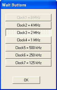
The 2 MHz clock is probably best for general-purpose use. Slower clocks may be needed for 10-bit ADC operation in high-precision applications. Faster clocks can be used where speed is more important than accuracy.
The table below shows typical sample rates for a single ADC channel at each clock speed, for 8-bit and 10-bit operation:
                   ----- Sample Rates -----
    ADC speed        8-bit          10-bit
     4 MHz          156 kHz        127 kHz
     2 MHz          104 kHz        89.4 kHz
     1 MHz          58.6 kHz       55.2 kHz
     500 kHz        33.2 kHz       31.2 kHz
     250 kHz        17.8 kHz       16.6 kHz
     125 kHz        8927 Hz        8927 Hz
If you want to try the 8 MHz clock you can comment out the following line in the Btn4 handler (IF.Ctrls=8) in the Dscope_Ctrls subroutine. Just add a semicolon in front of it:
WaitBtns#0x=0 ;Disable 8 MHz Btn 0
However, even if this works on your device, the accuracy will be quite poor. You might consider going to the ultimate in the speed vs resolution tradeoff, and simply switch from Analog to Digital inputs; you'll get up to 8 channels with a sample rate over 400 kHz.
Interrupt Lock:
The Interrupt Lock button (Btn5, on the Oscillators and Misc dialog page only) is normally off. When toggled on, it forces input acquisition to be locked to the Oscillator Interrupt Rate, instead of using the Sample Delay control on the main dialog page.
You will most likely want to use Interrupt Lock whenever you are using oscillators, since the oscillator interrupts will otherwise cause jitter in the sample delay. However, using interrupts will greatly reduce the maximum input sample rate. See the Interrupt Lock - Rate Limits topic below, and Freeze-Up Recovery after that.
Please note that with Interrupt Lock active you can't use negative Trigger Delay.
Interrupt Lock - Rate Limits:
In Interrupt Lock mode with Analog or Digital inputs active (the normal case unless you are using the Wave1k wavetable oscillator), there are limits to how many oscillators and input channels you can have active at any given Interrupt Rate. If you try to do too much, too fast, the DaquinOscope will freeze up and you will need to use the Freeze-Up Recovery method in the next subtopic.
The following are tables of approximate rate limits for various configurations. No Osc is when only the inputs are active. 1 Osc to 4 Osc refers to the number of square-wave oscillators active along with the inputs. Wave256 is when Osc0 is set to "pin 14" to get a 256-sample wavetable oscillator for use with an R-2R DAC on pins 2-9, with inputs but no square wave oscillators active. (You can use up to 3 square wave oscillators along with Wave256. The limits aren't shown here, but should be similar to the 2 Osc to 4 Osc cases.)
Note that with Digital inputs active, the number of channels doesn't matter since all 8 are always acquired, and the Channels control just determines whether 1, 2, 4, or 8 are shown.
There are two tables; the first is for general use including the use of inputs only (no oscillators), or inputs plus the 256-sample wavetable, or square wave oscillators that use arbitrary pins 2-13.
Interrupt Rate limits in kHz:
Arbitrary Osc pins 2-13:
    Channels    No Osc   1 Osc   2 Osc   3 Osc   4 Osc  Wave256
    1 Analog      50      38      29      23      21      40
    2 Analog      30      25      20      17      15      25
    4 Analog      18      16      14      12      11      16
  1-8 Digital     50      38      29      18      16      48
The second table is for inputs plus oscillators on pins 10-13 only, using a more efficient square wave scheme:
Fast Osc pins 10-13 only:
    Channels             1 Osc   2 Osc   3 Osc   4 Osc
    1 Analog              50      43      35      32
    2 Analog              32      25      23      21
    4 Analog              18      15      14      13
  1-8 Digital             50      43      40      35
Freeze-Up Recovery:
When Interrupt Lock is active and the Interrupt Rate is too high for the number of oscillators and input channels, DaquinOscope will freeze up. To recover, first unplug the Arduino USB connector. DaquinOscope will un-freeze, at which point you should close it normally. When prompted to save a DscopeSetup file, hit Escape or Cancel to simply exit.
Now plug the USB connector back in and re-start DaquinOscope as desired.
8/10 ADC Bits:
The 8/10 ADC Bits button (Btn6, on the Oscillators and Misc dialog page only) defaults to 8 ADC Bits.
The default 8-bit mode will resolve only 256 levels over the full-scale range, whereas 10-bit mode will resolve 1024.
The maximum sample rate (Sample Delay = 0) will be higher in 8-bit mode than in 10-bit. Typical values:
            1 ch     2 ch     4 ch
  8-bit     104618    47302    24270
  10-bit     89448    43302    22679
Note, however, that 10-bit mode does not support negative Trigger Delay. If you set negative delay while in 8-bit mode, the ADC Bits button will be forced to 8 bits and disabled.
In addition, 10-bit mode does not allow use of either wavetable oscillator, since it uses both the 1024 bytes of Arduino memory needed for the Wave1k oscillator, and the 256 bytes needed for the Wave256 oscillator.
8-bit mode uses only 1024 bytes of memory, so the Wave256 oscillator is allowed. The ADC Bits button will be forced to 8 bits and disabled when Wave256 has been selected.
Saving DaquinOscope Setups:
When you hit the OK button to exit DaquinOscope you will see a Windows file Save As dialog prompting you to save the current setup as DscopeSetup. That's the name of the default setup that you will be prompted to use when DaquinOscope next starts up. You can save under a different name, such as one that describes the intended use.
Then on start-up you can select that name from the list of files presented, or accept the DscopeSetup default, or hit Cancel or the Escape key to use the built-in defaults.
Note that not all control settings will be restored from the file. In particular, the Trigger state will be forced off. This is a protection against the common case where there is no trigger signal at start-up because some external source is not active yet, or the signal level is below the Trigger Level. If Trigger was selected, there would be no visible screen activity; the Arduino would be spending all its time waiting for an event that never comes, and the DaquinOscope controls would be unresponsive unless Auto Trigger was selected. Even then, at the default Auto-Trigger Delay of 1 second, control response would be very sluggish. By always starting with Trigger off, you can make sure you have the proper signal and/or trigger levels before toggling it on.
Also, at start-up the Oscillators OFF state is forced to prevent accidents, such as where the equipment to be driven by the oscillator signals is not ready to receive them. Or, worse yet, it is ready, and your 10 ton stamping press starts up before you are ready!
However, all other oscillator control settings are restored, including pin numbers, frequencies, and phases, and if a wavetable oscillator was in use its waveform file will be loaded and ready when Oscillators ON is toggled.
Variable, Control, and Array Usage:
The following summary of variable, control, and array usage is intended to aid in understanding the macro script operation. It can also help in modifying the script, including avoiding accidental re-use of critical variables.
Variables:
C      Oscillator phase cycle counter size (2^25 or 2^32)
D      Full-Scale Digital range, Volts
E      Square Osc jitter error
G      Square Osc jitter (Glitch) period
H      Trigger Holdoff, secs
J      Square Osc Jitter freq
K      Full-scale Analog range, Volts
N      Square Osc samples per phase
P      Osc Phase Start, percent
R      Sample rate display update limit
S      Interrupt rate for Osc or Int Lock
T      Timer var for Holdoff
X      Work var
Z      Osc freq (Ctrl3 working value)
Q0     Osc number to be adjusted
Q1     Work var (_Acq_Mode, Ctrl2, Btn1 pin)
QA     0 = Analog, 1 = Digital Inputs
QC     Display chans (1,2,4, or 8 for Digital)
QD     Trigger Delay, (-1023 to +32767)
QH     Trigger Hyst (0-255)
QI     _Write general loop index
QL     Trigger Level (0-1023)
QM     Trigger mode command
QN     _Write digital upload trace index
QP     Osc Phase Start, internal value
QR     Displayed sample rate
QS     Trigger Slope (0 = Rising, 1 = Falling)
QT     Trigger state
QW     Auto-trigger wait (neg=integer sec, else sec/64u)
QX     _Write digital bit index, also effective chans for sample rate
Qa     Task state
Qb     0 = 8-bit, 1 = 10-bit
Qc     Trigger pin (A0 default)
Qd     0 = Analog trig (1 = Digital)
Qi     Interrupt Lock
Qm     Digital Mode 0-3
Qn     0 = Auto, 1 = Normal Trigger
Qo     Oscillator state (0=off, 1=on)
Qr     0=5V FS range, 2=1.1V
Qv     Digital trace view map
Qw     Auto-trigger Wait control variable (10m-32767 sec)
UA     ADC clock 1-7
UC     Ctrl1 trigger pin selection number
UD     Sample Delay
UF     Auto-Increment File names (0, 1, 2)
UI     Misc loop counter
UM     ADC channel map or digital input options
UN     Work var (Btn4)
UR     _Write work var and sample rate
US     Osc step working variable
UT     Elapsed acquisition time, usec
UV     Save Ch during _Task
UX     Work var (Btn4)
UZ     File name continuation (0,1,2)
Ub     Master ADC pins bitmap
Uc     Bitmap of display chans
Ud     Scale factor for Digital In display
Um     Work var (Btn4)
Ut     Interrupt timer load value (1-255).  Ut=2e6/S - 1

Custom Controls:
Ctrl0  Sample Delay
Ctrl1  Trigger Pin, Trigger Delay, Oscillator Phase
Ctrl2  Trigger Level, Auto-Trigger Delay, Osc. Interrupt Rate
Ctrl3  Trigger Hysteresis, Trigger Holdoff, Oscillator Frequency
Btn0   Analog/Digital Inputs, Set Oscillator N
Btn1   Trigger toggle
Btn2   N Channels, Oscillator Pin N
Btn3   Rising/Falling Trigger, Oscillators ON/OFF
Btn4   Analog/Digital Pins, ADC Clock
Btn5   Auto/Normal Trigger, Interrupt Lock
Btn6   Save Data File, Digital Mode N, 8/10 ADC Bits
Btn7   Dialog page change: Main Controls, Trigger Timing, Osc and Misc

Arrays:
Buf0-Buf7      Setup load/save, Chan 0-7 display data buffers
Str1           Data file name and path
Str6           _Get_String text prompt and entry
Str7[200]      Misc labels
Str7[1400]     Digital view bitmaps
Str7[1600]     Oscillator settings
Str7[1700]     Wave oscillator file name
DaquinOscope Macro Listing:
;<Help=H4922
Posn#0="Ardu"
Posn#1=0
@_ComDev_Scan

Str1="Dscope"           ;Default data file
D=5.00                  ;Full-Scale Digital range
Qr=0                    ;0 = 5V analog range, 2 = 1.1V
Qr=Qr&2                 ;Allow only 0 or 2
IF.Qr=0
    K=5.00                  ;5V Full-scale Analog range
ELSE.
    K=1.10                  ;1.1V range
ENDIF.
H=0                     ;No trigger Holdoff
T=0                     ;Null holdoff timer
R=0.01                  ;1% sample rate display change limit
QR=0                    ;Current displayed sample rate
Qi=0                    ;1 = Interrupt Lock
Qm=0                    ;Digital Mode (0 = pins 0-7)
Q0=0                    ;Set Osc 0 default
S=10k                   ;Default int rate for Osc
Ut=199                  ;Timer load for 10 kHz int rate
UD=0                    ;Sample Delay
QL=512                  ;Default Trig Level
QH=5                    ;Default Trig Hyst
QA=0                    ;Default to Analog input display
QC=1                    ;Default single-chan display

UF=2                    ;Auto-increment file name if main AutoInc on
UZ=0                    ;Do not continue prior name series
Posn#0=UF               ;0=no AutoInc, 1=AutoInc, 2=main AutoInc state
Posn#1=UZ               ;0=no continue, 1=continue prior, 2=prior DaquinOscope
GetFilePath=2           ;Prior DATA file path
Str1[0]=FileName?P +z   ;Prior path and name without extension
IF.((UZ&1) && Str1[0])=0    ;If no name or no continue flag:
    Str1="Dscope"               ;Use default Data file
    AutoInc#Bu=-1               ;Reset name series
ENDIF.

Ud=1000                 ;Scale factor for Digital In (1024 = FS)

UA=3                    ;Default ADC clock 3 = 2 MHz

QT=0                    ;Default Trig off
Qn=0                    ;Auto-Trig default
Qw=1                    ;Auto-Trig wait = 1 sec
QW=-1                   ;Default 1 sec Auto-Trigger wait
QD=0                    ;Default = no trigger delay
Qd=0                    ;Default Analog trig (1=Digital)
Qc=0                    ;Default A0 trigger pin
QS=0                    ;Default Trig Slope = Rising

Qb=0                    ;0=8-bit, 1=10-bit ADC
Ub=b1111                ;Master ADC bitmap default

UI=2
WHILE.UI=<14                ;Set pins 2 - 13 as INPUTs
    Port#D2=h40D0 + UI
    UI=UI+1
WEND.

Port=$(hF0) + "b" + $(h80)  ;Clear acquisition flags

Msg=
Close=
Spect=0
Sgram=0
Trig=0
TrigDelay=0
ZeroScrnInd=1                  ;Individual screen zero posns
Zero=1                         ;Main Zero on
Mtr1=                          ;Remove Mtr1
Mtr0="<F(50)"                  ;Set default Mtr sizes
Mtr1="<F(50)"
Btn7=0

Str7=
Str7[200]="Trigger Level"
Str7[225]="Auto-Trigger Wait, sec"
Str7[250]="Osc. Interrupt Rate, Hz"
Str7[300]="Trigger Hysteresis"
Str7[325]="Trigger Holdoff, sec"
Str7[350]="Oscillator "
Str7[370]=" Freq, Hz"
Str7[400]="Analog Inputs"
Str7[420]="Digital Inputs"
Str7[500]="OFF"
Str7[510]="ON"
Str7[700]="Rising Trigger"
Str7[720]="Falling Trigger"
Str7[800]="Analog Pins"
Str7[825]="Digital "
Str7[850]="ADC Clock"
Str7[900]="Auto Trigger"
Str7[920]="Normal Trigger"
Str7[940]="Pins 0-7"
Str7[950]="Pins 2-9"
Str7[960]="Pins 6-13"
Str7[970]="Pins 8-15"
Str7[1000]="Digital Mode"
Str7[1025]="8 ADC Bits"
Str7[1050]="10 ADC Bits"

Str7[1100]="Analog Pin "
Str7[1120]="Digital Pin "
Str7[1140]="Wave Osc 0"

Str7[1200]#d=h08060200            ;4-byte array = 0, 2, 6, 8 (UNUSED)
Str7[1220]="Clock1 = 8 MHz"
Str7[1240]="Clock2 = 4 MHz"
Str7[1260]="Clock3 = 2 MHz"
Str7[1280]="Clock4 = 1 MHz"
Str7[1300]="Clock5 = 500 kHz"
Str7[1320]="Clock6 = 250 kHz"
Str7[1340]="Clock7 = 125 kHz"

;Digital View defaults:
Str7[1400]#b=b00111100          ;Mode 0 = view pins 2,3,4,5
Str7[1401]#b=b00001111          ;Mode 1 = view pins 2,3,4,5
Str7[1402]#b=b00111100          ;Mode 2 = view pins 8,9,10,11
Str7[1403]#b=b00001111          ;Mode 3 = view pins 8,9,10,11

;Str7[1500] to Str7[1531] = Osc0-3 frequencies (8 bytes each)   Z
;Str7[1540] to Str7[1555] = Osc0-3 step sizes (4 bytes each)    US
;Str7[1560] to Str7[1591] = Osc0-3 phases (8 bytes each)        P
;Str7[1600] to Str7[1615] = Osc0-3 accum start (4 bytes each)   QP
;Str7[1620] to Str7[1623] are pins for Osc0 to Osc3            (Q1)
Str7[1620]#b=0              ;Osc0 output pin
Str7[1621]#b=0              ;Osc1 output pin
Str7[1622]#b=0              ;Osc2 output pin
Str7[1623]#b=0              ;Osc3 output pin
Str7[1624]="0011111111111234"   ;Pin num index (0-15) to [1639]
Str7[1640]=" (OFF)"             ;Pin = 0, 1
Str7[1652]=""                   ;Pins 2-12
Str7[1664]=" (LED)"             ;Pin 13
Str7[1676]=" (Wave256)"         ;Pin 14
Str7[1688]=" (Wave1k)"          ;Pin 15
;Str7[1699] is flag byte, non-null if Wave Osc file uploaded
;Str7[1700] to [1799] is Wave Osc file name loaded to Arb7

Buf7="<Load:DscopeSetup"
IF.Posn?f=1             ;Load OK?
    Str7[0]#A=Buf7[0](aE)       ;Restore strings from Buf7[0]-[255]
    Buf7#Br=3                   ;Restore vars from Buf7[300]-[399]
    UF=Posn?0                   ;Replace saved UF, UZ
    UZ=Posn?1
    IF.UZ=2                     ;Use prior-session name, if any?
        Str1[0]#A=Buf7[400](aC)     ;Restore string from Buf7[400]-[463]
    ENDIF.
    Q1=Str7?b[1620]         ;Osc 0 Pin number
    IF.Q1=>13               ;Wave Osc?
        IF.Str7?b[1699]="U"
            A.ArbX7=                ;Remove current Arb7 wave
            A.Arb7=Str7[1700]       ;Open file for Arb7
            US=2^32 * Z / S
            IF.Q1=14                ;256-sample Wave?
                Port#a7=$(hF0) + "o"    ;Upload 256-byte data to Arduino
            ELSE.                   ;Else 1024-sample Wave
                T=2^31                  ;Block display updates
                Mtr1="No display with 1024-sample Wave"
                Port#A7=$(hF0) + "O"    ;Upload 1 Kbyte data to Arduino
            ENDIF.
        ENDIF.
    ENDIF.
ENDIF.

IF.QD=<0                            ;Set trigger delay display
    TrigDelay#N=QD
ELSE.
    TrigDelay#N=QD * QR / 1e6
ENDIF.
Port=$(hF0) + "D" + $w(QD)  ;Set trigger delay

QT=0                    ;Trigger OFF
Qo=0                    ;Oscillators OFF
Port=$(hF0) + "F" + $(hC0)      ;Set Oscs off
Port=$(hF0) + "I" + $(Ut)       ;Set default int rate
Port=$(hF0) + "A" + $(UA)       ;Set ADC clock
Port=$(hF0) + "b" + $(Qb+Qr)    ;Set 8-bit or 10-bit mode

Ctrls="<<DaquinOscope - Main Controls"

Ctrl0="<S(0,10000)"        ;Sample Delay range 0-10000 usec
Ctrl0="<p(0)"                  ;No decimal places
Ctrl0="<<Sample Delay, usec"   ;Control label
Ctrl0=UD                       ;Initial setting
Ctrls=0                        ;Control number for @_Dscope_Ctrls
IF.Qi=1                        ;Interrupt Lock on?
    Ctrl0="<D"                     ;Disable Sample Delay if so
    QR=0                           ;Force Sample Rate display update
ENDIF.
@_Dscope_Ctrls                 ;Run IF.Ctrls=0 code to set delay

Ctrl1="<<Trigger Pin"          ;Control label
Ctrl1="<r(0,18)"               ;Read-only slider range
Ctrls=1                        ;Control number for @_Dscope_Ctrls
@_Dscope_Ctrls                 ;Set trigger pin

Ctrl2="<S(0,1023)"             ;Trigger Level range 0-1023 samples
Ctrl2="<p(0)"                  ;No decimal places
Ctrl2="<<" + Str7[200]         ;Control label = "Trigger Level"
Ctrl2=QL                       ;Initial setting
Ctrls=2                        ;Control number for @_Dscope_Ctrls
@_Dscope_Ctrls                 ;Set trigger level

Ctrl3="<S(0,255)"              ;Trigger Hysteresis range 0-255
Ctrl3="<p(0)"                  ;No decimal places
Ctrl3="<<" + Str7[300]         ;Label = "Trigger Hysteresis"
Ctrl3=QH                       ;Initial setting
Ctrls=3                        ;Control number for @_Dscope_Ctrls
@_Dscope_Ctrls                 ;Set trigger hysteresis

Btn0="<T"                      ;Analog/Digital Inputs button
Btn0=QA                        ;Initial state
Ctrls=4                        ;Control number for @_Dscope_Ctrls
@_Dscope_Ctrls                 ;Set Analog/Digital mode and label

Btn1="<T"                      ;Trigger toggle
Btn1=QT                        ;Initial state
Btn1="Trigger"                 ;Button label
Ctrls=5                        ;Control number for @_Dscope_Ctrls
@_Dscope_Ctrls                 ;Set trigger state

Btn2="<M(QA + 2)"              ;Chan modes 0-2 for Analog, 0-3 Digital
Btn2=log2(QC)                  ;Channel count 1,2,4 or 1,2,4,8
Ctrls=6                        ;Control number for @_Dscope_Ctrls
@_Dscope_Ctrls                 ;Set channel count and button label

Btn3="<T"                      ;Rising/Falling Trigger (slope) button
Btn3=QS                        ;Initial state
Ctrls=7                        ;Control number for @_Dscope_Ctrls
@_Dscope_Ctrls                 ;Set button label and trigger slope

Btn4="<M"                      ;Momentary pushbutton
IF.QA=0
    Btn4="" + Str7[800]                    ;"Analog Pins"
ELSE.
    Btn4="" + Str7[825] + Str7[940 + 10 * Qm]   ;"Digital Pins 0-7", etc
ENDIF.

Btn5="<T"                      ;Auto/Normal Trigger toggle
Btn5=Qn                        ;Initial state
Ctrls=9                        ;Control number for @_Dscope_Ctrls
@_Dscope_Ctrls                 ;Also sets Auto-Trigger Wait

Btn6="<M"                      ;Momentary button
Btn6="Save Data File"

Btn7="<M(2)"                   ;3-state pushbutton
Btn7=0
Btn7="More Controls >>>"

Qv=Str7?b[1400 + Qm]           ;Set View for Digital Mode

@_Dscope_Acq_Mode              ;Sets UM ADC bitmap from Ub

Qa=0                           ;Initial task state
Task="_Dscope_Task"

UI=0                           ;Clear channel data Buf0-3
WHILE.UI=<4
    Ch=UI                          ;Set BufN number
    BufV="<=(0)"                   ;Fill BufN with nulls
    UI=UI+1                        ;Next BufN
WEND.

Buf0#Ch=0                      ;Display buttons show Ch0, etc
Buf0#Vx=1                      ;Allow Vert units w/o User Units tog
Mtr0="<<Sample Rate"           ;Mtr0 title

@_Dscope_Ctrls=Ctrls           ;Open Custom Ctrls dialog
Task="-_Dscope_Task"           ;Uninstall task when Ctrls closed
UI=0                           ;Disable all BufN channel displays
WHILE.UI=<8
    Ch=UI                          ;Set BufN number
    BufV="<d-"                     ;Disable BufN display
    UI=UI+1                        ;Next BufN
WEND.
Mtr0=                          ;Close Sample Rate Mtr0
Mtr1=                          ;Close info display if active
Port=$(hF0) + "F" + $(hC0)     ;Set Oscs (and ints) off
Buf0#d=0                       ;No upload auto-display
Buf0#Vx=0                      ;Restore normal Vert axis
Buf0#VU=0                      ;Normal vertical units
Buf0#Ch=-1                     ;Restore normal Display buttons
TrigDelay=0                    ;No Trigger Delay
Spect=0                        ;Force off to enable Zero
Sgram=0
Zero=0                         ;Toggle Zero off
Port#O=0                       ;Close COM port

Buf7[0]#aE=Str7[0,2047]        ;Save string data to Buf7[0]-[255]
Buf7#Bs=3                      ;Save variables to Buf7[300]-[399]
Buf7[400]#aC=Str1[0,511]       ;Save filename string to Buf7[400]-[463]
Buf7="<Save:DscopeSetup"       ;Save DaquinOscope setup
_Dscope_Acq_Mode Macro Subroutine Listing:
;<Help=H4922
;On entry, Ub holds master ADC bitmap
;QC holds current chans (1, 2, 4, 8)
;Returns with new UM = ADC or Digital mode bitmap

TrigDelay=0                    ;Reset for Xpand change, adj later
IF.Qi=1                        ;Ints on?
    IF.QD=<0                       ;Neg Trig Delay?
        QD=0                           ;Force 0 if so
        Port=$(hF0) + "D" + $w(QD)     ;Set new Trig Delay
    ENDIF.
ENDIF.

IF.Spect=1                     ;Spectrum on?
    Spect=0                        ;Force waveform display
ENDIF.
IF.Sgram=1                     ;Spectrogram on?
    Sgram=0                        ;Force waveform display
ENDIF.

IF.QC=1                        ;1-channel display?
    Xpand=0                        ;No X expand if so
    Uc=b0001                       ;Display single chan on L.IN
    LI.ZeroScrnAdj=100             ;Show w. 0 at bottom
    TraceMag=1                     ;2x vert. magnification
ENDIF.

IF.QC=2                        ;2-channel display, 512 samples each?
    IF.QA=0                        ;Analog display?
        Xpand=1                        ;X expand ON
        XpandMax#N=511                 ;Samples 0-511 fill screen width
        XpandMin#N=0
        IF.QD=<-511                    ;Trig Delay too neg?
            QD=-511                        ;Limit Trig Delay
            Port=$(hF0) + "D" + $w(QD)     ;Set new Trig Delay
            IF.Btn7=1                      ;Trig Delay ctrl visible?
                Ctrl1=QD                       ;Show new Trig Delay
            ENDIF.
        ENDIF.
    ENDIF.
    Uc=b0011                       ;Display 2 chans, LI and RI
    LI.ZeroScrnAdj=0               ;LI (Ch0) at screen top
    RI.ZeroScrnAdj=100             ;RI (Ch1) at screen bottom
    TraceMag=0                     ;1x vert. magnification
ENDIF.

IF.QC=4                        ;4-chan display, 256 samples each?
    IF.QA=0                        ;Analog display?
        Xpand=1                        ;X expand ON
        XpandMax#N=255                 ;Samples 0-255 fill screen width
        XpandMin#N=0
        IF.QD=<-255                    ;Trig Delay too neg?
            QD=-255                        ;Limit Trig Delay
            Port=$(hF0) + "D" + $w(QD)     ;Set new Trig Delay
            IF.Btn7=1                      ;Trig Delay ctrl visible?
                Ctrl1=QD                       ;Show new Trig Delay
            ENDIF.
        ENDIF.
    ENDIF.
    Uc=b1111                       ;Display 4 chans
    LI.ZeroScrnAdj=-50             ;Ch0 at screen top
    RI.ZeroScrnAdj=0
    LO.ZeroScrnAdj=50
    RO.ZeroScrnAdj=100             ;Ch3 at screen bottom
    TraceMag=-1                    ;0.5x vert. magnification
ENDIF.

IF.QC=8                        ;8-chan only available for Digital
    Uc=b1111                       ;Display 4 chans via upload, 4 direct
    TraceMag=-2                    ;0.25 x vert. magnification
    UI=0                           ;Channel counter
    UX=1                           ;Upload channel bit posn
    UN=0                           ;Upload channel count
    WHILE.UI=<8
        Ch=UI                          ;BufN chan
        IF.((UX & Qv) && !(UN & 4))    ;Bit set, and UN<4?
            BufV="<d-"                     ;Upload, disable direct
            Ch=UN                          ;Set upload chan
            Ch.ZeroScrnAdj=25 * UI - 75    ;Vertical zero posn
            UN=UN+1                        ;Count upload chan
        ELSE.                          ;Else direct display
            BufV="<dWU2"                   ;Show unipolar waveform, dotted
            BufV#Z=(7 - UI) * 256 / 8      ;Vertical zero posn
        ENDIF.
        UX=UX << 1                     ;Next upload chan bit posn
        UI=UI+1                        ;Next chan 0-7
    WEND.
ELSE.                          ;Else 1, 2, 4 chans via upload
    UI=0                           ;Chan counter 0-7
    WHILE.UI=<8                    ;Disable direct chan displays for all
        Ch=UI                          ;Set BufN for chan
        BufV="<d-"                     ;Disable direct display
        UI=UI+1                        ;Next chan
    WEND.
ENDIF.

Buf0#d=Uc                      ;Arduino chan priority
;Buf0#d=Uc & (~Posn?A)               ;Optional main chan priority

IF.QA=0                        ;Analog acq mode?
    Q1=1                           ;Moving bit
    Um=0                           ;Resulting bitmap
    UN=QC                          ;Num ADC chans (1, 2, 4)
    UI=0
    WHILE.UI=<6
        UX=Ub & Q1                     ;Isolate target bit
        IF.UX=>0                       ;Was it set?
            Um=Um | UX                     ;Set in result if so
            UN=UN-1                        ;Count the bit
            IF.UN=0                        ;Done with all QC bits?
                LoopBreak=2                    ;Exit WHILE loop
            ENDIF.
        ENDIF.
        Q1=Q1 << 1                     ;Next higher bit to test
        UI=UI+1                        ;Next ADC pin
    WEND.
    UM=Um + (Qi << 6)              ;New ADC bitmap
ELSE.                          ;Else Digital mode
    UM=h80 + Qm + (Qi << 6)        ;Else new digital mode command
ENDIF.

IF.QD=<0                       ;Negative trigger delay?
    TrigDelay#N=QD                 ;Restore if so
ELSE.
    TrigDelay#N=QD * QR / 1e6      ;Else restore pos delay, if any
ENDIF.
_Dscope_Ctrls Macro Subroutine Listing:
;<Help=H4922 IF.Ctrls=0 ;Ctrl0 = Sample Delay UD=Ctrl0 ;Get control value Port=$(hF0) + "s" + $w(UD) ;Set new sample delay ENDIF. IF.Ctrls=1 ;Ctrl1 IF.Btn7=0 ;Main dialog, Trigger Pin? Btn5=0 ;Force Auto-Trig UC=UC + Ctrl1?u ;Get new control up/down value IF.UC=>18 ;Out of range? UC=18 ;Limit range if so ENDIF. IF.UC=<0 ;Under range? UC=0 ;Limit to 0 if so ENDIF. Ctrl1#s=UC ;Update slider with new value IF.UC=<6 ;Analog pins 0-5? Ctrl1="< " + Str7[1100] + UC ;"Analog Pin nn" Qd=0 ;0 = Analog trigger Qc=UC ;Trigger pin ELSE. ;Else Digital control range 6-18 UI=UC - 6 + 2 ;6 => Digital pin 2 IF.UC=18 ;Max control value? Ctrl1="< " + Str7[1140] ;"Wave Osc 0" ELSE. Ctrl1="< " + Str7[1120] + UI ;"Digital Pin nn" ENDIF. Qd=1 ;1 = Digital trigger Qc=UI ;Trigger pin ENDIF. QM=QT<<7 + Qd<<6 + QS<<5 + Qc ;Trig mode cmd value Port=$(hF0) + "T" + $(QM) + $w(QL) ;Set Trigger mode ENDIF. IF.Btn7=1 ;Trigger Timing, Trigger Delay? QD=Ctrl1 ;Get new control value IF.QD=<0 ;Negative? Ctrl1="<<NEG Trigger Delay, samples" ;Neg is in samples ELSE. ;Else pos is in usec Ctrl1="<<Trigger Delay, usec" ENDIF. Port=$(hF0) + "D" + $w(QD) ;Set Trigger Delay IF.QD=<0 ;Was it negative (samples)? TrigDelay#N=QD ;Set Daqarta to match ELSE. ;Else pos (usec) TrigDelay#N=QD * QR / 1e6 ;Convert to samples ENDIF. ENDIF. IF.Btn7=2 ;Osc dialog, Osc Phase? P=Ctrl1 ;Get 0-100% value Str7[1560 + 8 * Q0]#q=P ;Save qword in array IF.Str7?b[1620 + Q0]=>13 ;Wave Osc ("pin" 14 or 15)? QP=P/100 * 2^32 ;Wave accum start value ELSE. ;Else square wave osc QP=P/100 * 2^25 ;Square accum start value ENDIF. Str7[1600 + 4 * Q0]#d=QP ;Save dword in array IF.Qo=1 ;Oscs ON now? Port=$(hF0) + "F" + $(hC0) ;Set oscs OFF temp UI=0 ;Osc number counter WHILE.UI=<4 ;Set all oscs Q1=Str7?b[1620 + UI] ;Pin number US=Str7?d[1540 + 4 * UI] ;Freq step QP=Str7?d[1600 + 4 * UI] ;Phase accum value Port=$(hF0) + "F" + $(h80 + UI<<4 + Q1) + $d(US) + $d(QP) UI=UI+1 WEND. Port=$(hF0) + "F" + $(hC1) ;Set oscs back ON ENDIF. ENDIF. ENDIF. IF.Ctrls=h81 ;Ctrl1 slider IF.Btn7=0 ;Main dialog = Trig Pin Btn5=0 ;Force Auto-Trig UC=Ctrl1?s ;Get slider posn 0-18 IF.UC=<6 ;0-5 = Analog pins Ctrl1="< " + Str7[1100] + UC ;"Analog Pin nn" Qd=0 ;Analog trig mode Qc=UC ;Trig pin ELSE. ;Else Digital pins UI=UC - 6 + 2 ;Convert 6-18 to 2-14 IF.UC=18 ;Max control value 18? Ctrl1="< " + Str7[1140] ;"Wave Osc 0" ELSE. ;Else normal Digital pin Ctrl1="< " + Str7[1120] + UI ;"Digital Pin nn" ENDIF. Qd=1 ;Digital trig mode Qc=UI ;Trig pin ENDIF. QM=QT<<7 + Qd<<6 + QS<<5 + Qc ;Trig mode cmd Port=$(hF0) + "T" + $(QM) + $w(QL) ;Send to USB serial port ENDIF. ENDIF. IF.Ctrls=2 ;Ctrl2 IF.Btn7=0 ;Main dialog - Trigger Level? QL=Ctrl2 ;Get control value IF.QT=1 ;Trigger active? QM=QT<<7 + Qd<<6 + QS<<5 + Qc ;Trig mode cmd Port=$(hF0) + "T" + $(QM) + $w(QL) ;Send to port ENDIF. ENDIF. IF.Btn7=1 ;Trig Timing - Auto-Trig Wait? Qw=Ctrl2 ;Get control value IF.Qw=>2 ;More than 2 secs requested? QW=-Qw ;Set neg = integer secs ELSE. ;Else set in 64 usec steps QW=Qw / 64u ENDIF. Port=$(hF0) + "W" + $w(QW) ;Set Auto-Trigger Wait ENDIF. IF.Btn7=2 ;Osc/Misc - Interrupt Rate? Q1=Ctrl2?u ;Scroll button step IF.Q1=0 ;Direct edit (no scroll)? S=Ctrl2 ;Get requested rate, Hz Ut=cint(2M / S - 1) ;Int timer load value ELSE. ;Else slider Ut=Ut-Q1 ;Slide load value +/-1 IF.Ut=>255 ;Too large (freq too low)? Ut=255 ;Limit = 2M/256 = 7812.5 Hz ENDIF. IF.Ut=<39 ;Too small (freq too high)? Ut=39 ;Limit = 50 kHz ENDIF. ENDIF. S=2M/(Ut + 1) ;Sample rate from load value Ctrl2=S ;Set control to show it Port=$(hF0) + "I" + $(Ut) ;Set interrupt timer ENDIF. ENDIF. IF.Ctrls=3 ;Ctrl3 IF.Btn7=0 ;Main dialog - Trigger Hyst? QH=Ctrl3 ;Get Hyst value 0-255 Port=$(hF0) + "h" + $(QH) ;Set Hyst (single byte) ENDIF. IF.Btn7=1 ;Trigger Timing - Holdoff? H=Ctrl3 ;Get Holdoff value T=0 ;Reset Holdoff timer ENDIF. IF.Btn7=2 ;Osc/Misc - Osc Freq? Z=Ctrl3 ;Get new freq Str7[1500 + 8 * Q0]#q=Z ;Save in array IF.Str7?b[1620 + Q0]=>13 ;Wave osc (Wave256 or Wave1k)? C=2^32 ;Wave osc accum size US=C * Z / S ;Wave osc phase step ELSE. ;Else square osc C=2^25 ;Square osc accum size US=C * Z / S ;Square Osc phase step N=C / (2 * US) ;Steps per square phase E=abs(N - cint(N)) ;Error fraction per phase E=E / cint(N) ;Error fraction per sample J=E * S / 2 ;Jitter frequency G=1/J ;Jitter (Glitch) period Msg=J(0.6) + " Jitter Hz" _ +n +G + " Period sec" ENDIF. Ctrl3=US * S / C ;Actual freq to control Str7[1540 + 4 * Q0]#d=US ;Save phase step in array IF.Qo=1 ;Oscs ON now? Q1=Str7?b[1620 + Q0] ;Pin number Port=$(hF0) + "F" + $(h80 + Q0<<4 + Q1) + $d(US) + $d(0) ENDIF. ENDIF. ENDIF. IF.Ctrls=4 ;Btn0 = Analog/Digital or Osc number IF.Btn7=<2 ;Analog/Digital toggle? QA=Btn0 ;New state 0=Analog, 1=Digital Btn0="" + Str7[400 + 20 * QA] ;Analog/Digital Inputs label Btn2="<M(QA + 2)" ;0-2 if Analog, 0-3 if Digital IF.QA=0 ;Analog now? Btn4="" + Str7[800] ;Analog Pins IF.Btn2=3 ;Was Digital in 8-chan mode? Btn2=2 ;Cut back to 4 for Analog QC=2^Btn2 ;2^2 = 4 Btn2=""+QC + " Channel" ENDIF. X=K ;Vert range for analog ELSE. ;Else Digital now Btn4="" + Str7[825] + Str7[940 + 10 * Qm] ;Digital Pins label X=D * 2 ;Vert range for digital ENDIF. Buf0#Vs=X ;Spect magnitude scaling UI=0 ;Chan counter WHILE.UI=<4 ;4 chans shown on later file Open Ch=UI ;Chan to set BufV#Vf=X ;Vert range for file BufV#Uf="Volt" ;Vert units for file UI=UI+1 ;Next chan WEND. @_Dscope_Acq_Mode ;Set new UM mode bitmap IF.QA=0 ;Analog? Buf0#VU=K * 2 ;Set vert range ELSE. ;Else Digital Buf0#VU=D * 4 ENDIF. ELSE. ;Else Osc number Msg= ;Clear prior Ctrl3 Freq jitter msg Q0=Btn0 ;Osc number to adjust Btn0="Set Oscillator " + Q0 ;Label button Q1=Str7?b[1620 + Q0] ;Current output pin from array UX=Str7?b[1624 + Q1] - h30 ;Index 0-4 for pin text Btn2="Osc" + Q0 + " = Pin " + Q1 + Str7[1640 + 12 * UX] Ctrl1="<<" + Str7[350] + Q0 + " Phase, %" ;"Oscillator N Phase" Ctrl3="<<" + Str7[350] + Q0 + Str7[370] ;"Oscillator N Freq, Hz" Ctrl3="<S(0,25k)" ;Limit to 25 kHz Ctrl1=Str7?q[1560 + 8 * Q0] ;Osc Phase % from array Ctrl3=Str7?q[1500 + 8 * Q0] ;Osc Freq from array ENDIF. ENDIF. IF.Ctrls=5 ;Btn1 = Trigger toggle QT=Btn1 ;Get new trigger state Trig=QT ;Set main Daqarta trig to match QM=QT<<7 + Qd<<6 + QS<<5 + Qc ;Trig mode cmd Port=$(hF0) + "T" + $(QM) + $w(QL) ;Send to device ENDIF. IF.Ctrls=6 ;Btn 2 = # channels / Osc Pin IF.Btn7=<2 ;Num chans? QC=2^Btn2 ;1, 2, or 4 chans (or 8 if Digital) Btn2="" + QC + " Channel" ;Label button @_Dscope_Acq_Mode ;Set new UM mode bitmap ELSE. ;Else Osc Pin Mtr1= ;Clear status msg, if any Ch=6 ;Str6 used for _Get_String StrV="Pin Number: " ;Prompt text @_Get_String ;Get user entry Q1=StrV?E[Posn?3-1,Posn?5-2] ;Evaluate to extract user entry IF.Q1=<2 ;Invalid pin? Q1=0 ;Set 0 = OFF ENDIF. IF.Q1=>15 ;Invalid pin? Q1=0 ;Set 0 = OFF ENDIF. IF.Q0=0 ;Setting Osc 0? T=0 ;Clear Holdoff timer ENDIF. IF.(Q0 && sgn(Q1-13)=1 ;Q0=>0 AND Q1=>13? Msg="Only Osc0 allows Wave mode." ELSE. UI=4 ;In case Q1 = pin 0 IF.Q1=!0 ;Non-zero pin number? UI=0 ;Osc test counter WHILE.UI=<4 ;Scan all OscN IF.UI=!Q0 ;Different than current? IF.Str7?b[1620 + UI]=Q1 ;Matching pin? Msg="Output pin already in use." LoopBreak=2 ;Exit WHILE if so ENDIF. ENDIF. UI=UI+1 ;Next OscN to scan WEND. ENDIF. IF.UI=4 ;No matching pins? IF.(QD * QT)=>=0 ;If no neg Trig Delay, Btn6="<N" ;Enable ADC bits ENDIF. Z=Str7?q[1500 + 8 * Q0] ;Osc freq Ctrl3="<S(0,25k)" ;25 kHz range IF.Q0=0 ;Setting Osc0? T=0 ;Clear Holdoff timer ENDIF. IF.Q1=>13 ;Wave Osc? A.ArbX7= ;Remove current Arb7 wave Arb7= ;File Open dialog for Arb7 IF.Posn?f=1 ;Load OK? GetFilePath=1 ;Get full path+name+ext UX=FileName?N ;Dummy read of name IF.Posn?z=<99 ;Will it fit in storage? Str7[1700]=FileName?N + z ;Store name Str7[1699]="U" ;Flag = Named wave uploaded ENDIF. US=2^32 * Z / S ;Wave osc freq step IF.Q1=14 ;256-sample Wave? Port#a7=$(hF0) + "o" ;Upload data Mtr1="Forcing 8-bit ADC mode for 256-sample Wave" Qb=0 ;0=8 bits, 1=10 Btn6=Qb ;Force btn to 8 Btn6="<D" ;Disable changes Btn6="" + Str7[1025] ;Show 8-bit label Port=$(hF0) + "b" + $(Qb+Qr) ;Set 8-bit mode ELSE. ;Else 1024-sample Wave T=2^31 ;Block display updates Mtr1="No display with 1024-sample Wave" Port#A7=$(hF0) + "O" ;Upload data ENDIF. ENDIF. ELSE. US=2^25 * Z / S ;Square osc freq step ENDIF. Str7[1540 + 4 * Q0]#d=US ;Save freq step in array Str7[1620 + Q0]#b=Q1 ;Save new pin number UX=Str7?b[1624 + Q1] - h30 ;Pin number label index Btn2="Osc" + Q0 + " = Pin " + Q1 + Str7[1640 + 12 * UX] IF.Qo=1 ;Osc button ON? Port=$(hF0) + "F" + $(Q0<<4 + Q1) + $d(US) ;Set freq ENDIF. ENDIF. ENDIF. ENDIF. ENDIF. IF.Ctrls=7 ;Btn3 = Trigger Slope / Osc ON/OFF IF.Btn7=<2 ;Rising/Falling Trigger button? QS=Btn3 ;New slope state Btn3="" + Str7[700 + 20 * QS] ;Rising/Falling Trigger label IF.QT=1 ;Trigger active? QM=QT<<7 + Qd<<6 + QS<<5 + Qc ;Trig mode cmd Port=$(hF0) + "T" + $(QM) + $w(QL) ;Send to port ENDIF. ELSE. ;Else Osc ON/OFF button Msg= ;Clear old message, if any IF.Btn3=1 ;Oscs going ON? UI=0 ;Osc counter Q1=0 ;Freq / pin flags WHILE.UI=<4 ;Check all 4 oscs Q1=Q1 + (Str7?b[1620 + UI] && Str7?d[1540 + 4 * UI]) UI=UI+1 ;Next osc WEND. IF.Q1=0 ;No oscs set up? Btn3=0 ;Force to OFF Msg="Set Pin and Freq for at least one Osc" ELSE. ;Else at least one set Port=$(hF0) + "F" + $(hC0) ;Oscs OFF while setting UI=0 ;Osc counter WHILE.UI=<4 ;Set all oscs Q1=Str7?b[1620 + UI] ;Pin number IF.Q1=>13 ;Wave Osc? IF.Str7?b[1699]=0 ;Not uploaded yet? IF.Q1=14 ;Wave256? Port#a7=$(hF0) + "o" ;Upload 256 bytes ELSE. ;Else Wave1k Port#A7=$(hF0) + "O" ;Upload 1024 bytes ENDIF. Str7[1699]="U" ;Flag=uploaded ENDIF. ENDIF. QP=Str7?d[1600 + 4 * UI] ;Phase accum value US=Str7?d[1540 + 4 * UI] ;Freq step Port=$(hF0) + "F" + $(h80 + UI<<4 + Q1) + $d(US) + $d(QP) UI=UI+1 ;Next osc to set WEND. Port=$(hF0) + "F" + $(hC1) ;All set, Oscs ON ENDIF. ELSE. ;Else oscs going OFF Port=$(hF0) + "F" + $(hC0) ;Oscs OFF ENDIF. Qo=Btn3 ;New Osc ON/OFF state Btn3="Oscillators " + Str7[500 + 10 * Qo] ;Label ON/OFF ENDIF. ENDIF. IF.Ctrls=8 ;Btn4 = ADC/Digital Pins or ADC Clock select Btn4="<D" ;Disable during WaitBtns select IF.Btn7=2 ;Osc/Misc page? UI=0 ;ADC Clock index if so WHILE.UI=<7 ;7 clock rates to WaitBtns Ch=UI ;WaitBtns button index WaitBtns#V="" + Str7[1220 + 20 * UI] ;Set label from array UI=UI+1 ;Next index WEND. WaitBtns#R=1 ;Radio-button mode WaitBtns#0x=0 ;Disable 8 MHz Btn 0 Ch=UA-1 ;Mode 1-7 -> Btn 0-6 WaitBtns#V=1 ;Current mode on WaitBtns#N=7 ;7 ADC clock rates ELSE. ;Else Analog / Digital Pins IF.QA=0 ;Analog Inputs? UI=0 ;Button index WHILE.UI=<6 ;ADC pins 0-5 to WaitBtns Ch=UI ;WaitBtns button index WaitBtns#V="ADC Pin " + UI ;Set label from array UI=UI+1 ;Next button index WEND. WaitBtns#R=0 ;Independent buttons WaitBtns#b=Ub ;Master ADC bitmap WaitBtns#N=6 ;Only ADC pins 0-5 ELSE. ;Else Digital Inputs IF.Btn7=1 ;Trigger Timing dialog? Btn6="<D" ;No Digital Mode changes ENDIF. UX=Str7?b[1200 + Qm] ;0,2,6,8 start pin from Qm=0-3 UI=0 ;Button index WHILE.UI=<8 ;Set 8 digital pins buttons Ch=UI ;WaitBtns button index WaitBtns#V="Digital Pin " + UX ;Set label from array UX=UX+1 ;Next label index UI=UI+1 ;Next button index WEND. WaitBtns#R=0 ;Independent buttons WaitBtns#b=Qv ;Master Digital In view bitmap WaitBtns#N=8 ;Use all 8 buttons ENDIF. ENDIF. ENDIF. IF.Ctrls=h88 ;Return from WaitBtns IF.Btn7=2 ;Osc/Misc page? UA=WaitBtns?R + 1 ;Number of set button, 1-based Port=$(hF0) + "A" + $(UA) ;Set ADC clock rate Btn4="" + Str7[850] + Str7[1220 + 20 * (UA-1) + 6] ;ADC Clock label Btn4="<N" ;Re-enable button disabled above ELSE. ;Else Analog/Digital Pins IF.QA=0 ;Analog Inputs? UI=WaitBtns?b ;Get bitmap from WaitBtns UN=bcnt(UI) ;Count of pins set IF.UN=<QC ;Not enough for num chans? Msg="Must have at least" + QC + "pins selected" WaitBtns#N=6 ;Try again ELSE. ;Else at least 1 pin / chan Ub=UI ;New master ADC bitmap Btn2="<M(int(log2(UN)))" ;Limit Btn2 chans to match @_Dscope_Acq_Mode ;Set new UM mode bitmap Btn4="<N" ;Re-enable button Msg= ;Clear any error msg ENDIF. ELSE. ;Else Digital Inputs UI=WaitBtns?b ;Bitmap from WaitBtns UN=bcnt(UI) ;Number of pins set IF.QC=>4 ;8 chan mode? UX=4 ;Limit test to 4 chans ELSE. ;Else 1,2,4 chans UX=QC ;Actual chan count ENDIF. IF.UN=<UX ;Not enough for num chans? Msg="Must have at least" + UX + "pins selected" WaitBtns#N=8 ;Try again ELSE. ;Else at least 1 pin / chan Qv=UI ;New Digital In view map Str7[1400 + Qm]#b=Qv ;Store in byte array @_Dscope_Acq_Mode ;Set new UM mode bitmap Btn4="<N" ;Re-enable button IF.Btn7=1 ;Trigger Timing dialog? Btn6="<N" ;Allow Digital Mode changes ENDIF. Msg= ;Clear any error msg ENDIF. ENDIF. ENDIF. ENDIF. IF.Ctrls=9 ;Btn5 = Trigger Auto/Norm / Interrupt Lock IF.Btn7=2 ;Interrupt Lock? Qi=Btn5 ;Get new state, 1 = Int Lock IF.Qi=1 ;Int Lock now? Btn6="<D" ;Disable ADC Bits Ctrl0="<D" ;Disable Sample Delay IF.Qb=1 ;ADC Bits = 10? Mtr1="Forcing 8-bit ADC mode for Interrupt Lock" Qb=0 ;0 = 8 bits, 1 = 10 bits Btn6=Qb ;Set button for 8 bits Btn6="" + Str7[1025] ;Show 8-bit label Port=$(hF0) + "b" + $(Qb+Qr) ;Set 8-bit mode ENDIF. ELSE. ;Else Int Lock going off Btn6="<N" ;Enable ADC bits Ctrl0="<N" ;Enable Sample Delay ENDIF. @_Dscope_Acq_Mode ;Set new UM mode bitmap ELSE. ;Else Trig Auto/Norm Qn=Btn5 ;New Auto/Norm state Btn5="" + Str7[900 + 20 * Qn] ;Set button label IF.Btn5=0 ;Going to Auto? Port=$(hF0) + "W" + $w(QW) ;Set Auto-Trigger Wait ELSE. ;Else Normal Port=$(hF0) + "W" + $w(0) ;No Auto-Trigger Wait ENDIF. ENDIF. ENDIF. IF.Ctrls=10 ;Btn6 = File Save, Digital Mode, 8/10 ADC Bits IF.Btn7=2 ;Osc/Misc dialog = 8/10 ADC Bits? Qb=Btn6 ;0 = 8 ADC bits, 1 = 10 bits Btn6="" + Str7[1025 + 25 * Qb] ;Show label Port=$(hF0) + "b" + $(Qb+Qr) ;Set 8-bit or 10-bit mode ENDIF. IF.Btn7=1 ;Trigger Timing dialog = Digital Mode? Qm=Btn6 ;0-3 Digital Mode Qv=Str7?b[1400 + Qm] ;Set View for this mode Btn4="" + Str7[825] + Str7[940 + 10 * Qm] ;Digital Pins Btn6="" + Str7[1000] + Qm(0) + " = " + Str7[940 + 10 * Qm] @_Dscope_Acq_Mode ;Set new UM mode bitmap ENDIF. IF.Btn7=0 ;Main dialog = File Save? IF.QA=0 ;Analog inputs? Buf0#M=Ub ;ADC chan file save bitmap ELSE. ;Else Digital Buf0#M=Qv ;Digital chan file save bitmap ENDIF. Buf0#Rf=QR ;File sample rate Buf0#N=QC ;1, 2, 4, or 8 chans AutoInc#Bu=UF ;Filename AutoInc state (0,1,2) Buf0="<SaveDQA:" + Str1 ;Save As prompt IF.Posn?f=1 ;Name entered? GetFilePath=2 ;Get save path and name Str1[0]=FileName?P +z ;Save it without extension ENDIF. ENDIF. ENDIF. IF.Ctrls=11 ;Btn7 = Setup options IF.Btn7=0 ;Main dialog default? Ctrls="<<DaquinOscope - Main Controls" ;Dialog title Ctrl1="<<Trigger Pin" ;Control label Ctrl1="<r(0,18)" ;Pin range (ADC + dig + Wave Osc) Ctrl1#s=UC ;Set current pin select number IF.UC=<6 ;0-5 = ADC? Ctrl1="< " + Str7[1100] + UC ;"Analog Pin nn" ELSE. ;Else digital or Wave Osc UI=UC - 6 + 2 ;Slider number to digital pin 2-14 IF.UC=18 ;Slider at max? Ctrl1="< " + Str7[1140] ;"Wave Osc 0" ELSE. ;Else normal digital Ctrl1="< " + Str7[1120] + UI ;"Digital Pin nn" ENDIF. ENDIF. Ctrl2="<<" + Str7[200] ;"Trigger Level" Ctrl2="<S(0,1023)" ;Slider range Ctrl2="<p(0)" ;No decimal places Ctrl2=QL ;Control = current Level Ctrl3="<<" + Str7[300] ;"Trigger Hysteresis" Ctrl3="<S(0,255)" ;Slider range Ctrl3="<p(0)" ;No decimal places Ctrl3=QH ;Control = current Hysteresis Btn0="<T" ;Toggle button, Analog/Digital Btn0=QA ;Btn0 = current state Btn0="" + Str7[400 + 20 * QA] ;Analog/Digital Inputs label Btn2="<M(QA + 2)" ;Chans = Multi-state 0-2 or 0-3 Btn2=log2(QC) ;Current chans 1,2,4 or 1,2,4,8 Btn2="" + QC + " Channel" ;"N channel" label Btn3=QS ;Rising/Falling slope state Btn3="" + Str7[700 + 20 * QS] ;"Rising/Falling Trigger" IF.QA=0 ;Analog input mode? Btn4="" + Str7[800] ;"Analog Pins" ELSE. ;Else Digital inputs Btn4="" + Str7[825] + Str7[940 + 10 * Qm] ;"Digital Pins 0-7", etc ENDIF. Btn5="<T" ;Auto/Normal Trigger toggle Btn5=Qn ;Set current state Btn5="" + Str7[900 + 20 * Qn] ;Label button Btn6="<M" ;Momentary File Save button Btn6="<N" ;Enable Btn6="Save Data File" ;Label Btn7="More Controls >>>" ;This dialog change button label ENDIF. IF.Btn7=1 ;Trigger Timing dialog? Ctrls="<<DaquinOscope - Trigger Timing" IF.(Qb + Qi)=0 ;8-bit ADC, no Int Lock? Ctrl1="<S(-1023, 32767)" ;Allow negative Trigger Delay IF.QD=<0 ;Current delay negative? Ctrl1="<<NEG Trigger Delay, samples" ELSE. Ctrl1="<<Trigger Delay, usec" ENDIF. ELSE. ;Else 10-bit ADC Ctrl1="<S(0, 32767)" ;No neg delay Ctrl1="<<Trigger Delay, usec" ;Always usec IF.QD=<0 ;Current delay negative? QD=0 ;Force to 0 if so ENDIF. ENDIF. Ctrl1="<p(0)" ;No decimal places Ctrl1=QD ;Ctrl1 shows Trigger Delay value Ctrl2="<<" + Str7[225] ;"Auto-Trigger Wait, sec" Ctrl2="<S(10m, 32767)" ;10 ms to 32767 sec range Ctrl2="<p(3)" ;3 decimal places Ctrl2=Qw ;Show current Wait value Ctrl3="<<" + Str7[325] ;"Trigger Holdoff, sec" Ctrl3="<S(0,32767" ;0-32767 sec range Ctrl3="<p(3)" ;3 decimal places Ctrl3=H ;Show current Holdoff value Btn0="<T" ;Toggle button, Analog/Digital Btn0=QA ;Btn0 = current state Btn0="" + Str7[400 + 20 * QA] ;Analog/Digital Inputs label Btn2="<M(QA + 2)" ;Chans = Multi-state 0-2 or 0-3 Btn2=log2(QC) ;Current chans 1,2,4 or 1,2,4,8 Btn2="" + QC + " Channel" ;"N channel" label Btn3=QS ;Rising/Falling slope state Btn3="" + Str7[700 + 20 * QS] ;"Rising/Falling Trigger" IF.QA=0 ;Analog input mode? Btn4="" + Str7[800] ;"Analog Pins" ELSE. ;Else Digital inputs Btn4="" + Str7[825] + Str7[940 + 10 * Qm] ;"Digital Pins 0-7", etc ENDIF. Btn5="<T" ;Auto/Normal Trigger toggle Btn5=Qn ;Set current state Btn5="" + Str7[900 + 20 * Qn] ;Label button Btn6="<M(3)" ;0-3 Digital Modes Btn6="<N" ;Enable button Btn6=Qm ;Set current mode Btn6="" + Str7[1000] + Qm(0) + " = " + Str7[940 + 10 * Qm] ;Show it Btn7="Osc and Misc Controls >>>" ;Dialog change button label ENDIF. IF.Btn7=2 ;Osc/Misc dialog? Ctrls="<<DaquinOscope - Oscillators and Misc." Ctrl1="<S(0,99.9999)" ;Osc N Phase range Ctrl1="<p(4)" ;4 decimal places Ctrl1="<<" + Str7[350] + Q0 + " Phase, %" ;"Oscillator Q0 Phase" Ctrl1=Str7?q[1560 + 8 * Q0] ;Set Osc Q0 Phase from array Ctrl2="<S(7812.5,50k)" ;Interrupt rate rane Ctrl2="<<" + Str7[250] ;"Interrupt Rate" Ctrl2=S ;Set current rate S Ctrl3="<<" + Str7[350] + Q0 + Str7[370] ;"Oscillator N Freq, Hz" Ctrl3="<S(0,25k)" ;0-25000 Hz Freq range Ctrl3="<p(5)" ;5 decimal places Ctrl3=Str7?q[1500 + 8 * Q0] ;Set Osc Q0 Freq from array Btn0="<M(3)" ;0-3 OscN Btn0=Q0 ;Set Osc Q0 Btn0="Set Oscillator " + Q0 Btn2="<M" ;Momentary button for Osc Pin Q1=Str7?b[1620 + Q0] ;Get current pin number for Osc Q0 UX=Str7?b[1624 + Q1] - h30 ;Pin number text index Btn2="Osc" + Q0 + " = Pin " + Q1 + Str7[1640 + 12 * UX] ;"Osc0 = Pin 0 (OFF)" Btn3=Qo ;Oscillators ON/OFF state Btn3="Oscillators " + Str7[500 + 10 * Qo] ;Show ON or OFF Btn4="" + Str7[850] + Str7[1220 + 20 * (UA-1) + 6] ;ADC Clock label Btn5="Interrupt Lock" Btn5=Qi ;1 = Int Lock Btn6="<T" ;ADC Bits = Toggle-type button Btn6=Qb ;Set current state Btn6="" + Str7[1025 + 25 * Qb] ;"8 ADC Bits" or "10 ADC Bits" IF.Str7?b[1620]=14 ;Wave256 Osc loaded? OR.(QD * QT)=<0 ;OR Trigger, w. neg delay? Btn6="<D" ;Disable ADC Bits button ELSE. Btn6="<N" ;Else enable ENDIF. Btn7="Main Controls >>>" ;Dialog change button label ENDIF. ENDIF.
_Dscope_Task Macro Subroutine Listing:
;<Help=H4922

IF.Pause=1             ;Paused?
    LoopBreak=0                ;No update if so
ENDIF.

IF.Timer=<T            ;Trigger Holdoff time elapsed?
    LoopBreak=0                ;No update if not
ENDIF.

UV=Ch                  ;Save _Ctrls Ch
IF.Qa=0                ;Task state = ready to request next burst?
    Port=$(hF1) + $(UM)    ;UM = bitmap (+ 40h if ints)
    Qa=1                   ;Task state = burst requested
ENDIF.
IF.Qa=1                ;Waiting for 0xF1 return of acq time?
    UT=Port?4              ;Request elapsed acquisition time, usec
    IF.Port?n=!0           ;Any bytes read?
        T=Timer                ;Time of 0xF1 return
        ;Earliest time for next trigger:
        T=T - UT / 1e6 + H     ;(Current less acq time = trig time) + Holdoff
        IF.(UM & h80)=0        ;Analog (ADC) input mode?
            IF.Qb=1                ;10-bit ADC?
                Port#D1=hF2            ;Request 1280 bytes if so
            ELSE.
                Port#D1=hF3            ;Else request 1024 bytes for 8-bit
            ENDIF.
        ELSE.                  ;Else Digital input mode
            Port#D1=hF3            ;Request 1024 bytes for 8 digital pins
        ENDIF.
        Qa=2                   ;Task state = Data requested
    ENDIF.
ENDIF.
IF.Qa=2                ;Waiting for 1K samples?
    IF.(UM & h80)=0        ;Analog (ADC) mode?
        IF.QC=1                ;Single chan?
            IF.Qb=1                ;10-bit ADC?
                Buf0#A1=Port?A         ;Get 1K *samples* to Buf0
            ELSE.                  ;Else 8-bit ADC
                Buf0#b1=Port?a         ;Get 1K bytes to Buf0
            ENDIF.
        ENDIF.
        IF.QC=2                ;2 channels?
            IF.Qb=1                ;10-bit ADC?
                Buf0#A2=Port?A         ;Get 512 samples each to Buf0-1
            ELSE.                  ;Else 8-bit ADC
                Buf0#b2=Port?a         ;Get 512 bytes each to Buf0-1
            ENDIF.
        ENDIF.
        IF.QC=4                ;4 channels?
            IF.Qb=1                ;10-bit ADC?
                Buf0#A4=Port?A         ;Get 256 samples each to Buf0-3
            ELSE.                  ;Else 8-bit ADC
                Buf0#b4=Port?a         ;Get 256 bytes each to Buf0-3
            ENDIF.
        ENDIF.
    ELSE.                  ;Else Digital input mode
        Ch#n=(Qm + 1) & 2      ;0,2,2,0 bit offset for Qm modes 0,1,2,3
        Buf0#Dn=Port?D         ;Upload top viewmap button bit to Buf0
    ENDIF.
    IF.Port?n=!0           ;Any bytes read?
        @_Dscope_Write         ;Display if so
        Qa=0                   ;Reset task state for next update
    ENDIF.
ENDIF.
Ch=UV                  ;Restore _Ctrls Ch
_Dscope_Write Macro Subroutine Listing:
;<Help=H4922

IF.(UM & h80)=0        ;Analog mode?
    QI=0                   ;Channel index
    Ch=QI                  ;Index for BufV
    BufV="<uW0"            ;Always upload initial chan
    IF.Btn2=>0             ;2 or 4 chans?
        Ch=QI+1                ;Set 2nd chan index
        BufV="<uW1"            ;Upload 2nd chan
    ENDIF.
    IF.Btn2=2              ;4 chans?
        Ch=QI+2
        BufV="<uW2"
        Ch=QI+3
        BufV="<uW3"
    ENDIF.
    QX=QC                  ;Effective chans for sample rate
ELSE.                  ;Else Digital mode
    QX=1                   ;Bit posn marker
    QN=0                   ;Upload data chan 0-3
    IF.(QX & Qv)=>0        ;Does Buf0 need upload?
        Buf0="<uW(QN)"
        QN=QN+1
    ENDIF.
    QI=1                   ;Now Buf1-Buf7
    UR=(Qm + 1) & 2        ;0,2,2,0 bit offset for Qm modes 0,1,2,3
    WHILE.QI=<8
        Ch=QI
        Ch#n=(QI + UR) & 7
        BufV#Dn=Port?C
        QX=QX << 1
        IF.QN=<4
            IF.(QX & Qv)=>0        ;Bit set for upload?
                BufV="<uW(QN)"
                QN=QN+1
            ENDIF.
        ENDIF.
        QI=QI+1
    WEND.
    QX=1                   ;Effective chans for sample rate
ENDIF.

IF.(QD * QT)=<0        ;Negative trigger delay, w. active trig?
    Port#D1=h81            ;Delayed samples, low word
    UR=Port?2
    Port#D1=h82            ;Delayed samples, high word
    UR=(Port?2)<<16 + UR   ;Combined delayed N-chan samples
    UR=UR * 1e6 / UT       ;Delayed sample rate
    Port#D1=h83            ;Actual neg delay samples, abs val
    UP=Port?2
    UP=-UP                 ;Convert to neg
    IF.UP=!QD              ;Same as control setting?
        QD=UP                  ;Update if  not
        IF.Btn7=1              ;Trig delay showing?
            Ctrl1=QD               ;Update if so
        ENDIF.
    ENDIF.
ELSE.
    UR=1024e6 / UT / QX        ;Normal sample rate
ENDIF.

X=abs(UR-QR) / QR      ;Fractional change from display
IF.X=>R                ;Past limit?
    QR=UR                  ;Update if so
    Buf0#R=QR              ;Update X axis sample rate
    Buf0#Rf=QR             ;Update file sample rate
    Buf0#Rs=QR             ;Update Spectrum X axis
    Mtr0=QR + " Hz"        ;Update display
ENDIF.
See also Macro Examples and Mini-Apps, DaqPort Arduino Sketch, USB / Serial Communications Port Access
- Back to Sound Card Precision Phase Meter/Plotter/Logger Mini-App
- Ahead to Event Triggering
- Daqarta Help Contents
- Daqarta Help Index
- Daqarta Downloads
- Daqarta Home Page
- Donate to Daqarta
Questions? Comments? Contact us!
We respond to ALL inquiries, typically within 24 hrs.INTERSTELLAR RESEARCH:
Over 45 Years of Innovative Instrumentation
© Copyright 2007 - 2026 by Interstellar Research
All rights reserved